
Table Build
Article Index
In our 2015 and 2016 charity Texas Holdem tournaments we used "hole card" cameras but were limited to 4 cameras. This was due to the USB capture device used and the number of web cams it could use. While they work fine they took time to setup, where slightly in the way, and were seen by other hole card cameras.

Once it was decided to build a 9 camera table there was one simple rule. We must NOT modify the original table. The table is the official charity foundation table with a rather expensive cloth. Again - we can NOT touch the table in any way. Additional information - How we edit video and Examples of finished videos.
Gear Used
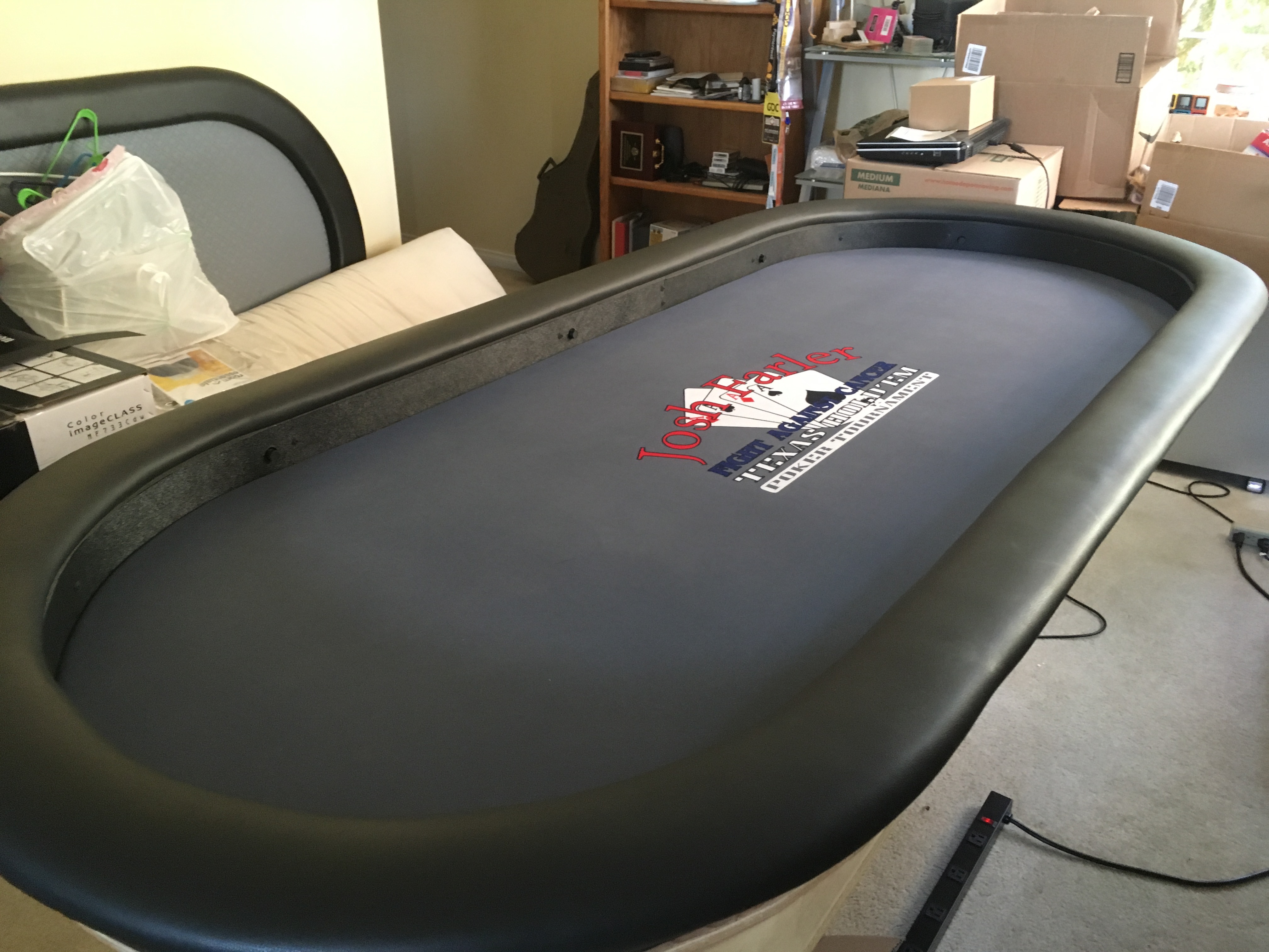
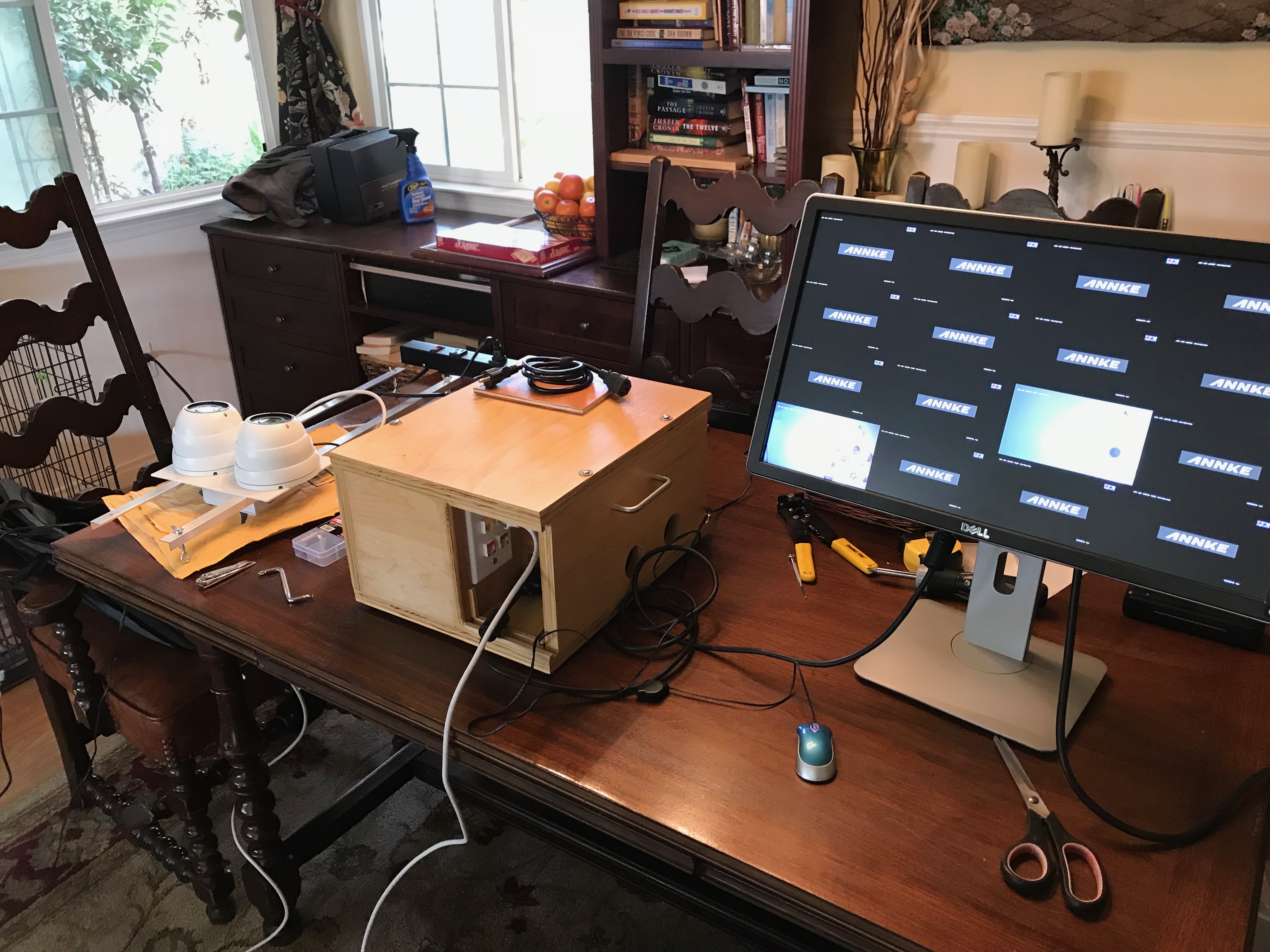
The first step was to purchase a small amount of equipment and test. We thought long and hard on the type of system we proposed, what it would take to maintain, the reliability, and of course the cost (ok this last part may have gotten away a bit). This image also shows the table with its padded rail.
One camera was purchased and tested with the existing USB system. Once this passed our quick test we purchased 9 cameras and tested them on our make shift "test bench" As each camera will get 1amp we tested with a 5 way splitter and a 5amp power supply.
This then progressed to a 9 camera test using a 10amp power supply. In order to not over power the cameras a 1amp light was added to the mix. This light not only uses the additional amp but will provide an indicator light on the connector panel. Our camera documenation only listed the camera power requirements as 0.5 amp OR HIGHER. We decided not to push this.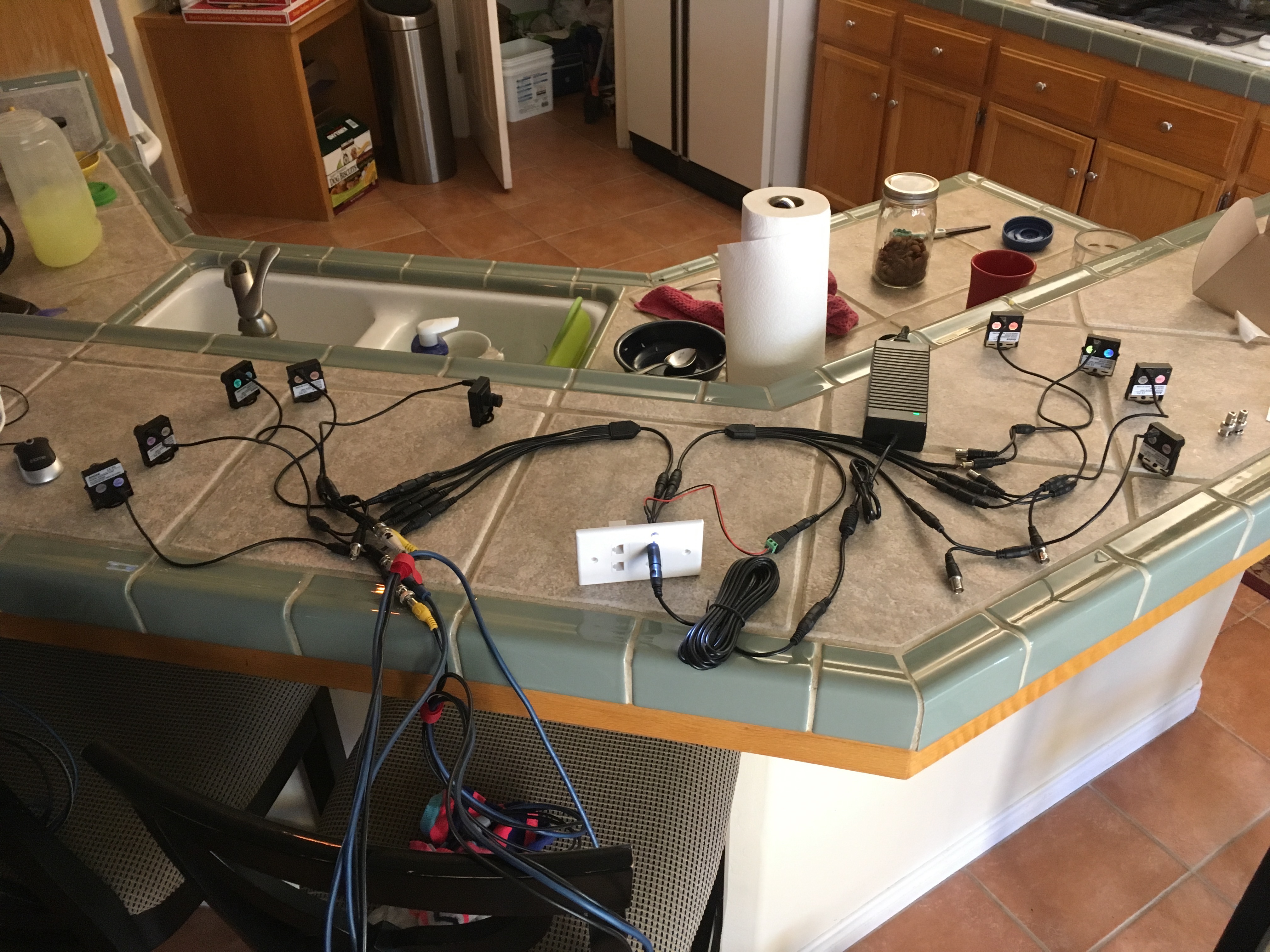
A list of all gear (equipment) used is found at the end of this article.
Camera Track
Once most of the items needed were purchased it was time to make the camera "track". Unbolting the padded rail from the play surface allowed us to place the play surface on a new piece of plywood. We also transferred the holes used to bolt the play surface to the padded rail. (important later) Once the oval was traced we drew the inner oval and cut out the 3 inch wide track. (image shows the support blocks being installed)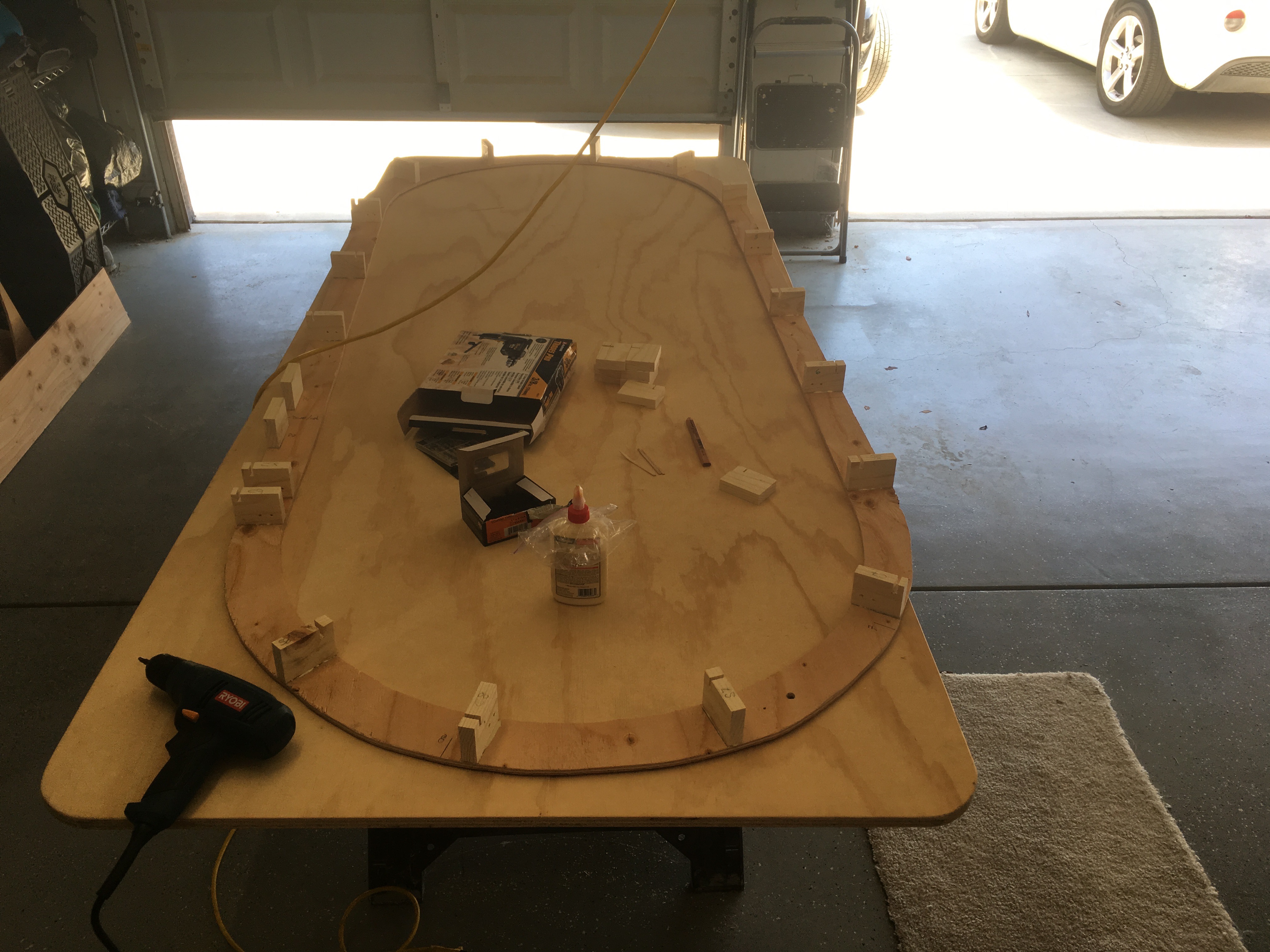
We determined that each camera needed a mounting block, that a block would be needed between each camera, the spot between seats 1 and 9 needed horizontal blocks to mount the cable keystone plate, and that camera 9 needed an additional block on its left side to keep the cables mass of cables away. Important to note - the plywood is 0.344 inch thick. This was important because we decided to make the camera track a total of 2.5 inches tall so we cut each mounting block 2.156 tall. (important later) You will also see that each block has a slot cut into the top for the wiring harnesses (more later) and that we predrilled the mounting holes in the camera blocks.The slots were alternated (front and rear) with the rear slots on the camera blocks. This ensured the wiring was behind the camera. Each block was glued and screwed from the bottom.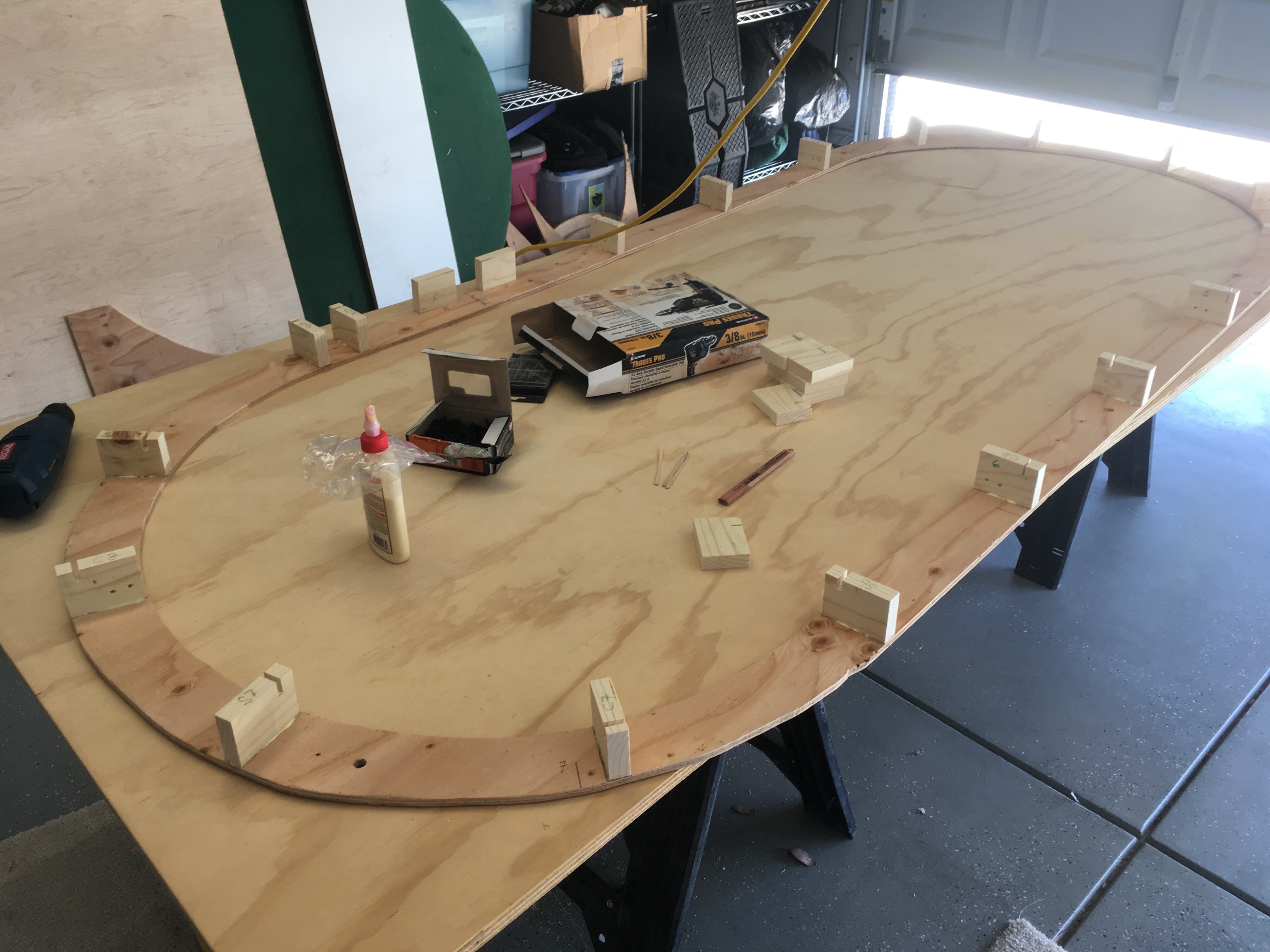
We then realized that IF the camera track covering has any gaps the players would see the wood blocks which may ruin the look. Because the covering (0.06 inch plastic) is black we painted the entire camera track black. The plastic was purchased in 8 foot strips that were cut 2.5 inch wide. We should also note that the plastic is textured on one side. This is great because it removed any chance of a reflection from the cards. Remember the track and mounting blocks combined are 2.5 inch tall (important later). (picture shows the inner covering being installed but without camera holes)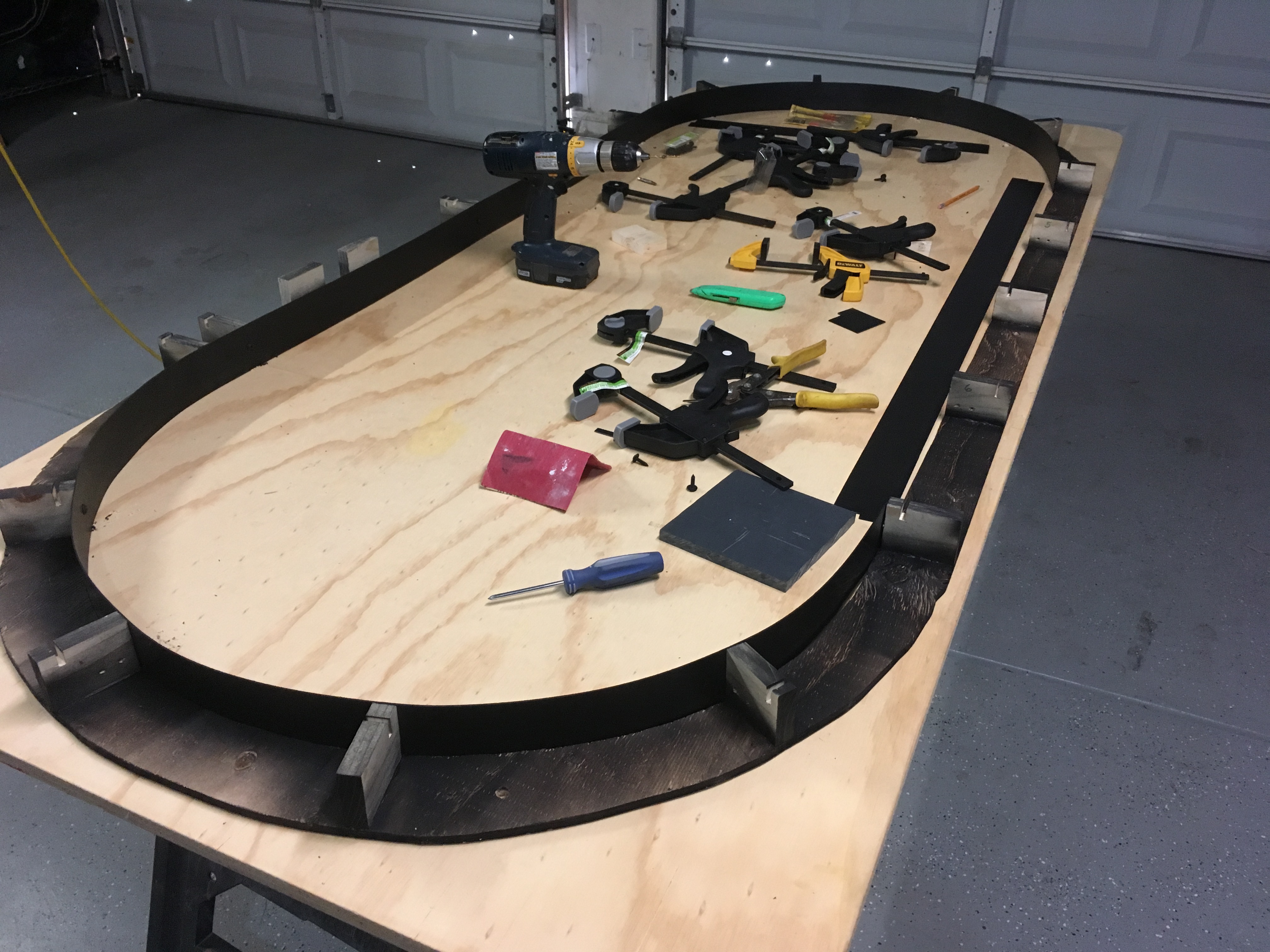
Once the inner covering was mounted we needed to cut the holes for the hole cameras to peek thru. By creating a jib from a spare mounting block (ya we cut way to many) we were able to use a new paddle bit, sized for the camera lens housing, to cut each hole. In the following image you can also see the camera block is predrilled for the camera mounting bracket.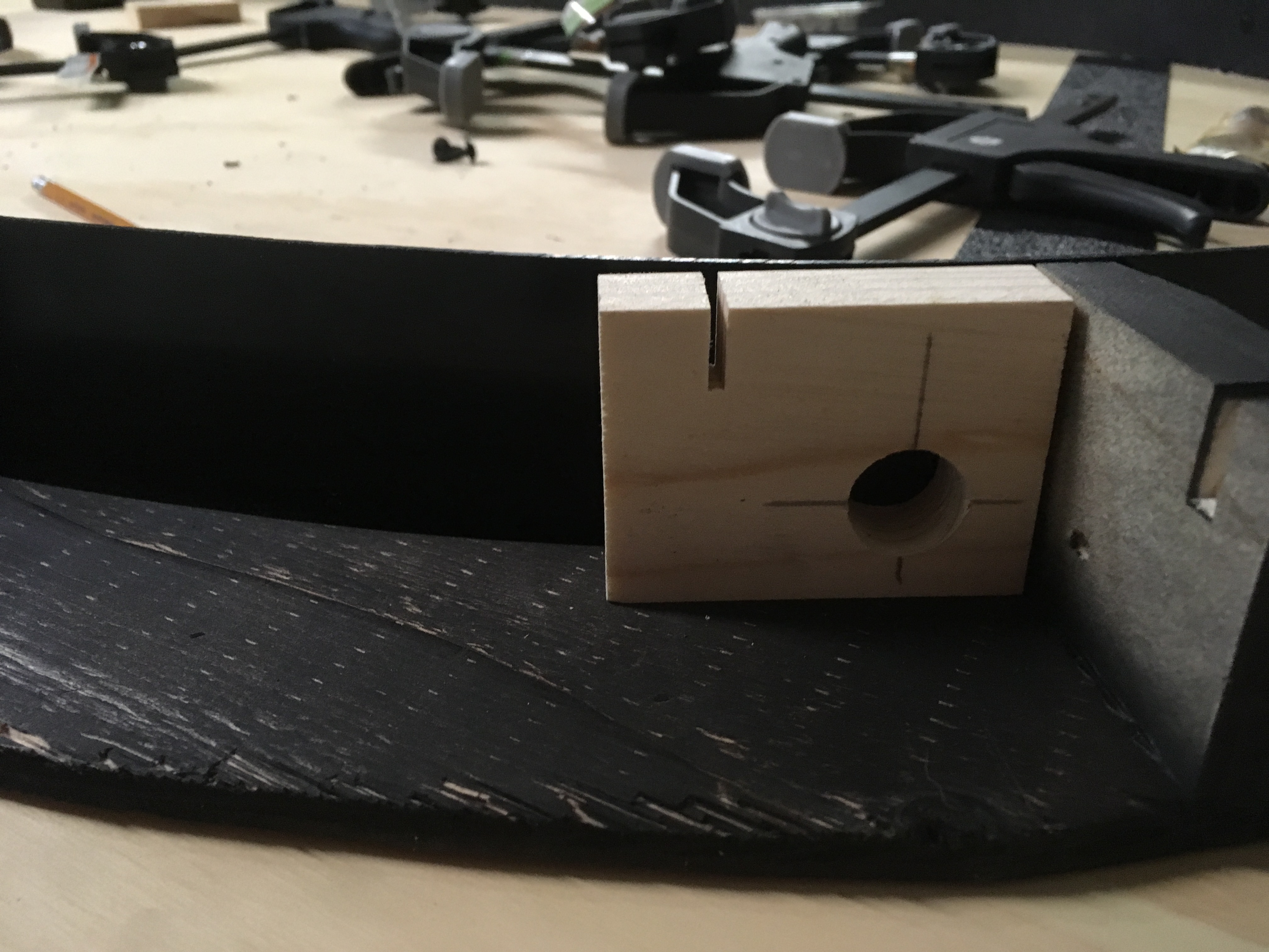
Electronics
At this point we have cameras that have BNC connectors, powered by 2.5mm DC, and we need to bring ALL of this to a central point. Once gathered we need to get the video signals and power off of the table to a recorder which we have not purchased yet but have done basic Internet research.
It was decided to use Cat5 network cable for the video camera feeds. Because Cat5 has 4 pairs (8 wires) we can get 4 cameras per cable and allows us to transfer the feeds thru a keystone plate between positions 1 and 9. Internally seats 2 to 5 use one cable, seats 6 to 9 use a second cable. Seat one, which we considered heavily, uses a third cable all by itself. The heavy consideration was due to the cost difference between an 8 camera and a 16 camera recording system.
The power to each camera was made from 2-wire doorbell wire. This provided the proper gauge needed and was cheap. We simply cut the required length to each camera and then wire tied them into a make shift wiring harness. Like the Cat5 network cable - cameras 2 to 5 and 6 to 9 are wire harnessed with camera 1 being seperate.
So, now we have wire for power and video to each camera but how to connect to the camera? UTP BALUN A balun allows traditional coax cable to be replaced by category 5 and other forms of twisted pair wire in CCTV video camera & surveillance installations. Thats right, we are basically building a CCTV camera system. By adding a BNC balun to the camera video output we attach the network pair to the balun. Using the Cat5 was great as each camera uses a coloured pair (such as the Brown Brown/White pair shown below) We then add a DC power balun to the power lead of the camera and wired it with the doorbell wire harness. At each block location we used shrink wrap to protect the wiring. This may have been overkill but we where already deep into the build and wanted to protect against any issues.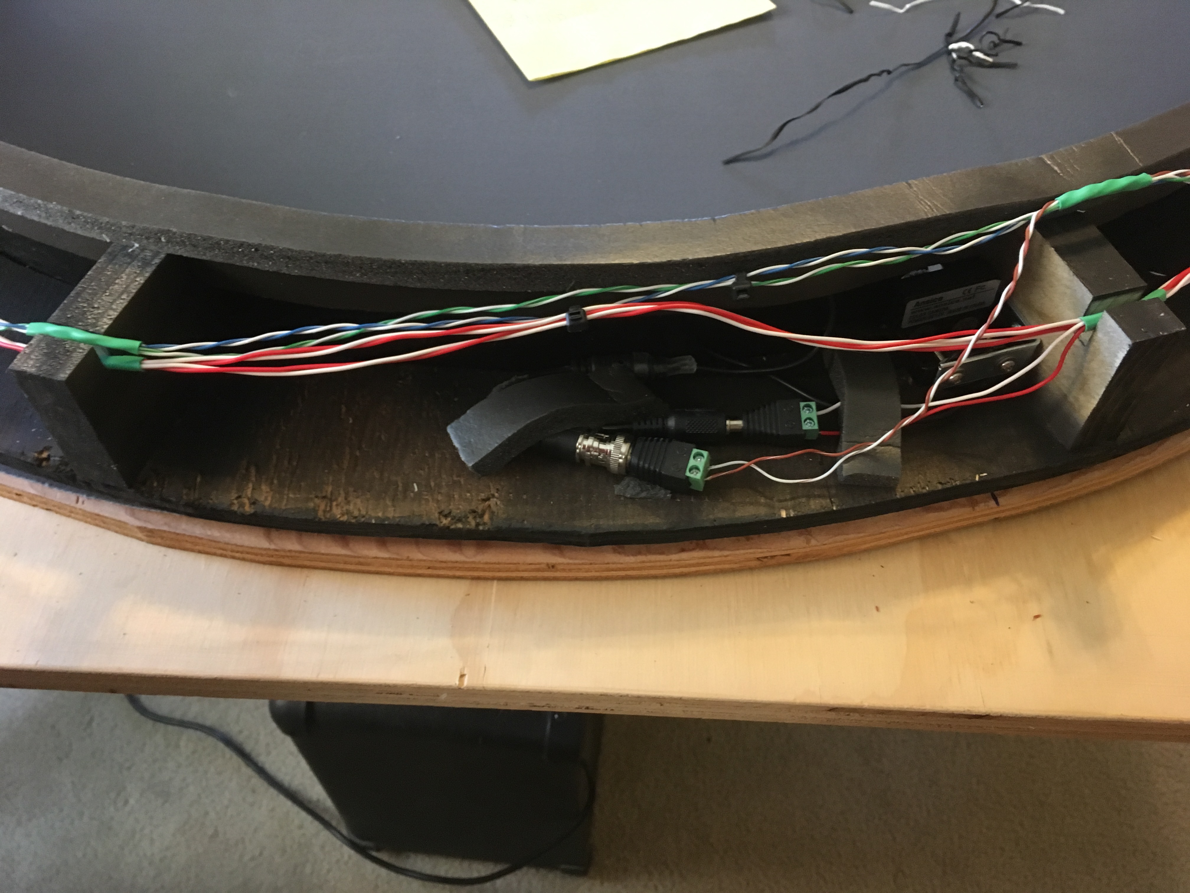
In this image we see seat 6, which is at the end of the power harness and cat5 cable, with the baluns attached. The foam tape strips were used to keep the wiring positioned. This foam was needed in a later step and the excess was used here. You can also see how the camera is attached to the mounting bracket which was first attached to the block. The tolerances here were very tight. We could not attach the bracket to the camera first because then there was no room to attach the bracket to the block. We also did not use washers on the nut side of the block allowing the nut to be "sucked into" to wood which then ensures the nut will not back off.
We also standardized the color coding for all of network and power wiring. All negative terminals use the "white" wire in the color wire pairs. Example: Camera 6 uses the Blue and Blue/White network cable wires for the video. The blue/white wire is the negative wire. Likewise the red/white wire on the power harness is used for the negative side of the DC power balun.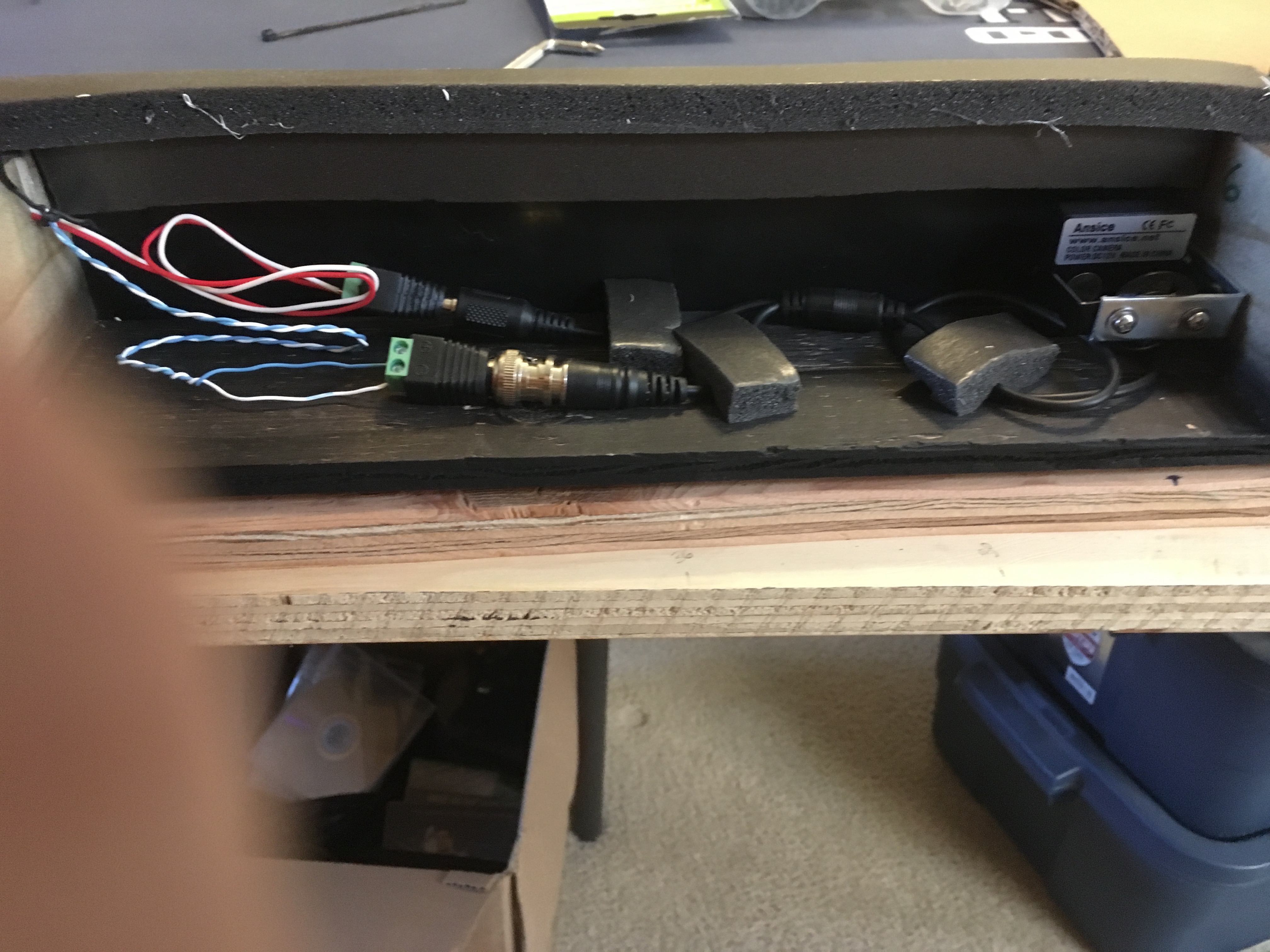
With each camera now connected to the power and video wiring harnesses it was time to address the connection point. Baluns were added to the end of power harness pairs and each cat5 pluged into the keystone connectors mounted into a shaved down wall plate. A word on the power system. We used a 10amp power supply with an extension to the table. A 2 to 1 splitter protrudes through a keystone blank (with a hole drilled in it to match the diameter and a slot cut to insert the splitter wire). Each side of the 2 way spliter is then split again using a 5:1 splitter making 10 power leads. 9 leads are then plugged into the power baluns with the 10th lead powering the LED light. All power baluns were shrink wrapped to their mating partners to ensure they will remain connected. We also made a "spreader plate" for the power baluns to ensure that no two baluns could touch their contact points. (screws) This was made from excess plastic from the camera track covering. As you can see this makes a very congested area behind the keystone plate and why we added the block near camera 9.
You can see we added a strip of black foam (weather trim) to the inside edge of the inner covering. We first attached the foam strip to the top of each support block next to the inner covering. We then attached a second strip to the inner edge of the first strip to create a "gasket" that would be sandwiched between the inner covering and the padded rails once it was reattached. This was needed because when we cut the camera track oval, and then decided to make it 3 inch wide, we messed up. During a "fit test" we discovered small gaps where the inner plastic covering did not fit well enough to hide the "magic". The following image shows the wiring connection point between seats 1 and 9 and the first foam strip.
Using the same plastic as the inner covering we wrapped the exterior of the camera track. The following image shows the tables keystone plate with the 3 network cable keystones, the power plug, and the power LED. Moving the LED ot the center was a bit of a trick as the corners of the keystone connectors has to be shaved. In the end there was just enough room to drop the nut straight down betwen them and use twizzers to turn it in place.
We condidered many options to make the power connector flush in the wall plate but in the end decided that the plug does not extend past the edge of the padded rail and being lazy was the final option. We also placed the cut in the keystone blank on the bottom edge to hide this from the casual viewer.
The 3 network plugs are colour coded (thank you to my daughter for the fingernail polish) making the setup more of a plug and play activity, more on this later)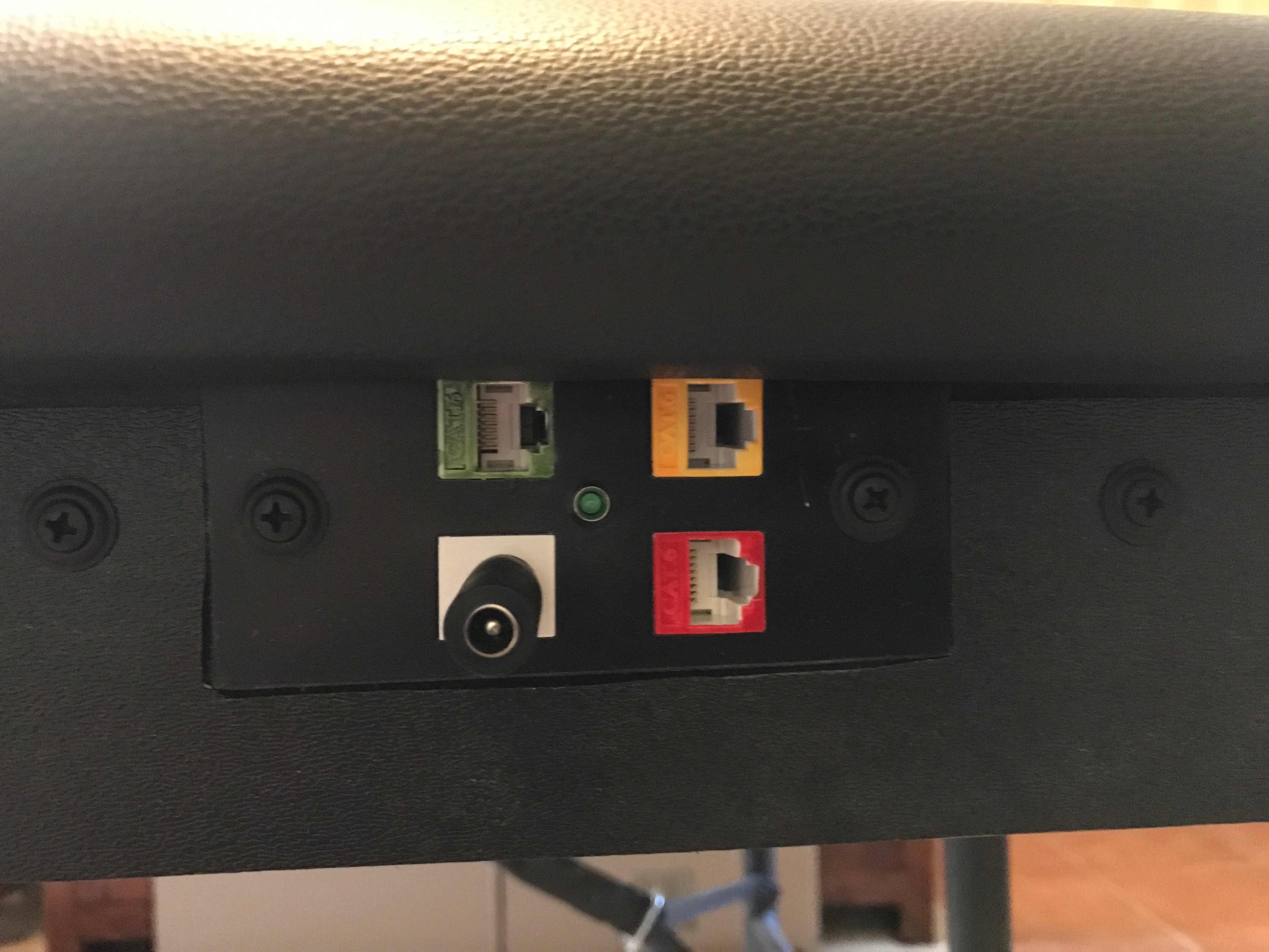
Each camera blends in pretty well we believe. Each camera location also received a single screw that holds the inner covering in place. The screws used to hold the plastic covering were unique as they have a small decorative washer attached. Oddly, these were found at an automotive store. We considered using velcro but felt that it would be insecure. 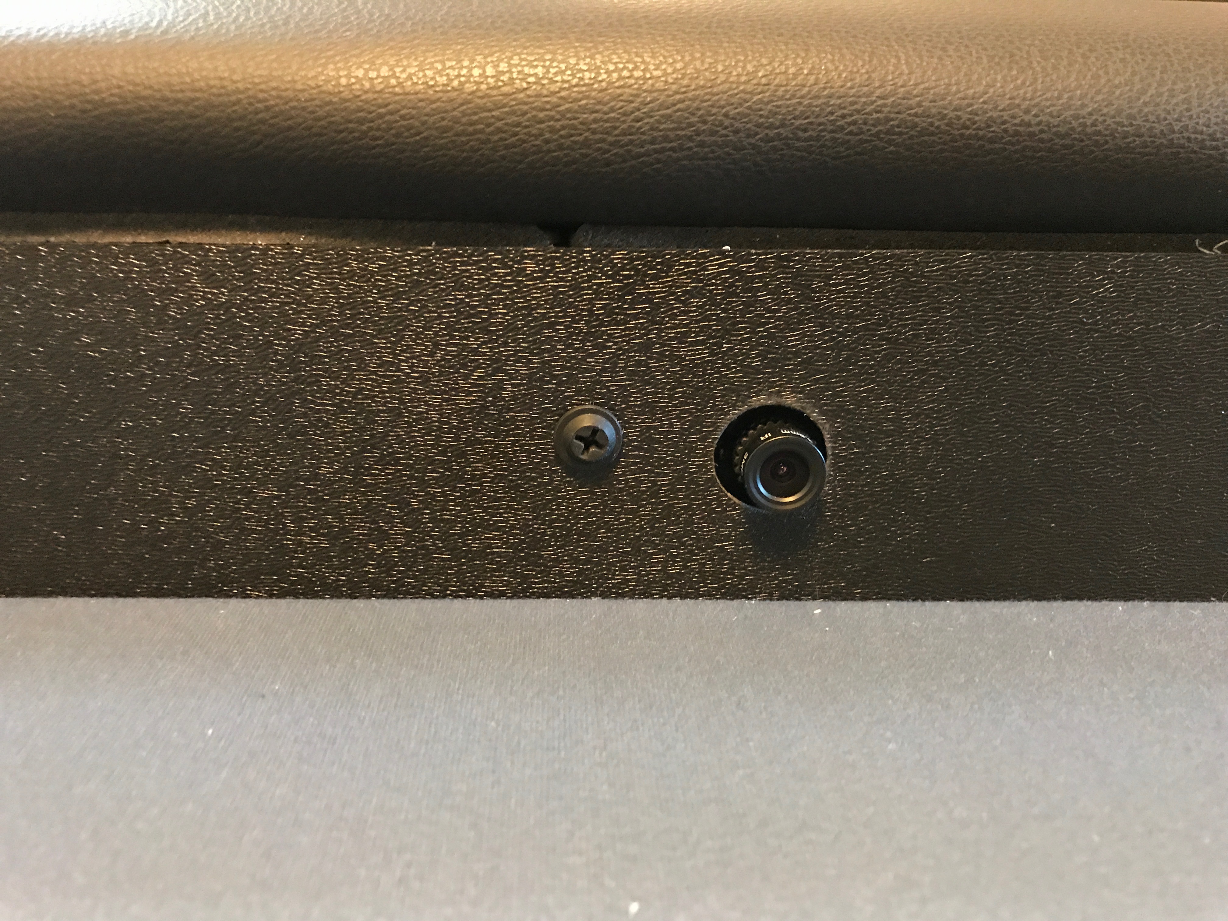
Now its time to mount the padded rail. This was originally done from the bottom side of the play surface, with 1.5 inch bolts, into tee nuts mounted in the padded rail. (we may post our initial table build later) The original bolts were replaced with 4 inch bolts. Remember the camera track is 2.5 inch tall? 4 - 1.5 = 2.5 :)
The original bolts were put in a zip lock bag and using excess foam strips (ya we had a lot left over) stored inside the camera track between seats 5 and 6. Think about this for a moment. All of the wires to seat 5 come clockwise and all of the wires to seat 6 come counter clockwise. This left a great area to store the original bolts. We now have the option to remove the camera track and using the original bolts reattach the rail thus reverting the table back to its original state.
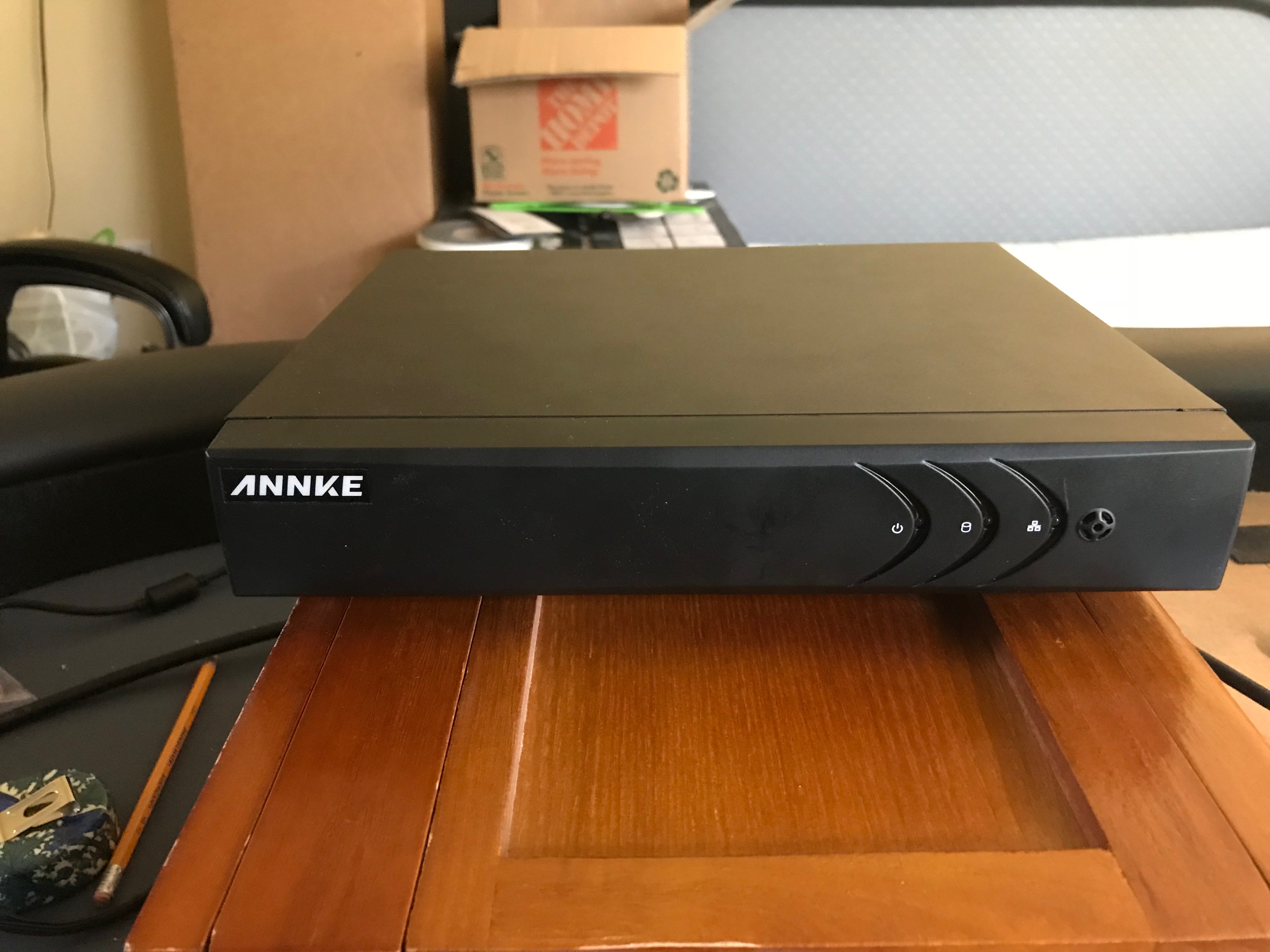
Now that the "table" is complete we still need a way to capture all of the video. Since we are building a CCTV system is only made since to use a security DVR recorder. These are typically sold as 4, 8, or 16 camera units. Like we said above the price difference between the 8 and the 16 was something we considered and decided to go ahead with the 16. This extra cost allowed for the 9th camera to be added to the table but also allows for additional "external" cameras to be added later.
As you may have already guessed we used baluns to convert the two wire cat5 wiring back to the BNC connection at the back of the DVR. This however made for a very sloppy and somewhat concerning situation. IF we just used this "as is" the wires would be prone to breaking. Note; we made short cat5 cables with a keystone connector to complete the circuit from the table. (see below) We did test the sytem at this point and knew we were doing well!
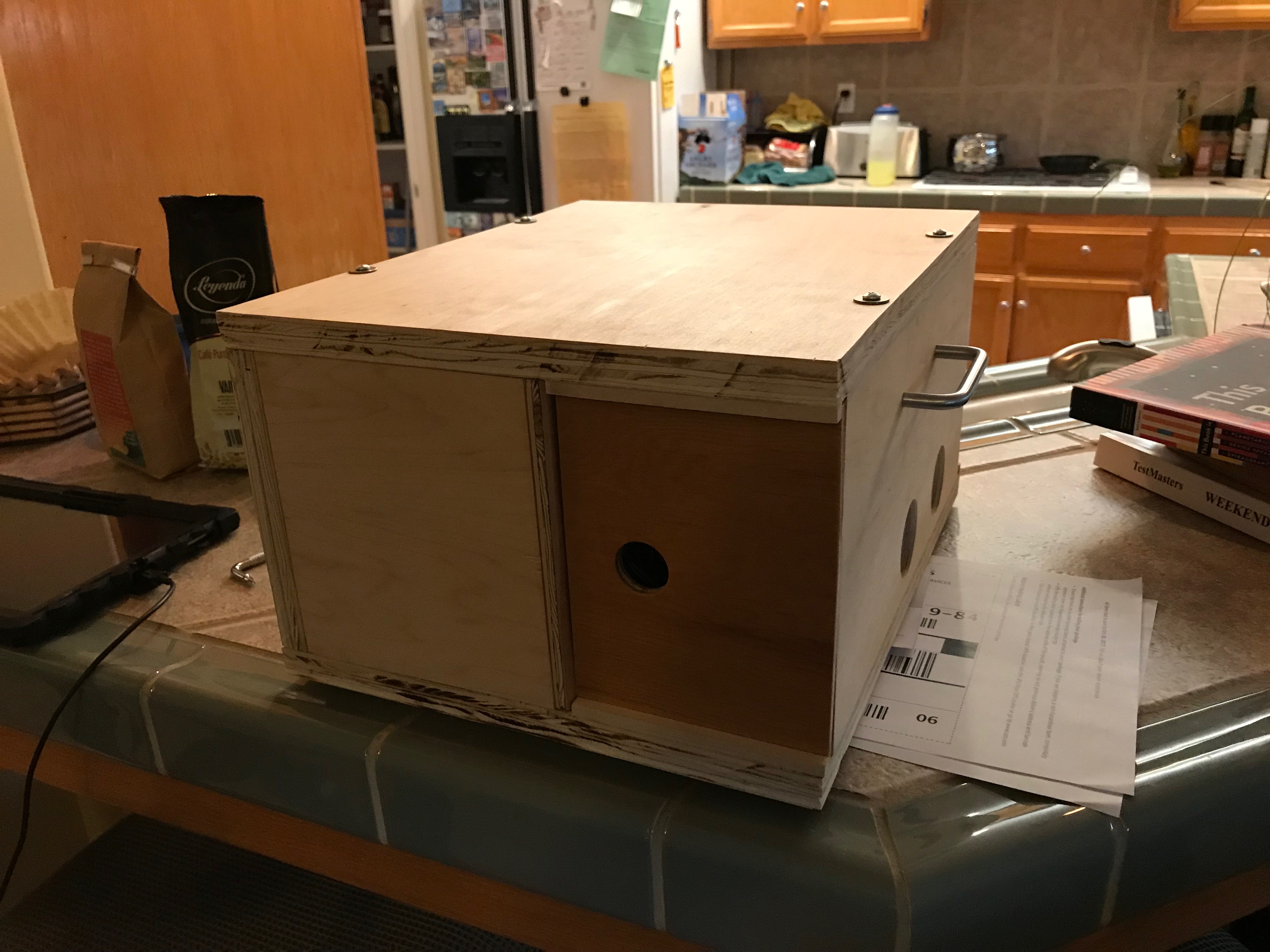
We played around with many options to protect the baluns and wiring but decided to build an enclosure (read as box) that would house the entire DVR. The box also will house the colour coded cat5 cables (that attach the table to the DVR) the power supplies (1 for the DVR, 1 for the table), the mouse, video adapter (VGA to DVI) and paperwork (DVR instructions and out written instructions) The image below shows the cabling and our first thought on a mouse/keyboard.
Using nothing but scrap wood from other projects and a whole lot of measuring we began construction. We decided to create sliding doors for the front and back of the box which made the box simpler and cheaper. The following image shows the door slide guides being glued into place and the keystone plate created to connect the network cables to the DVR wiring. The box was constructed entirely by my son who refused to let me do anything!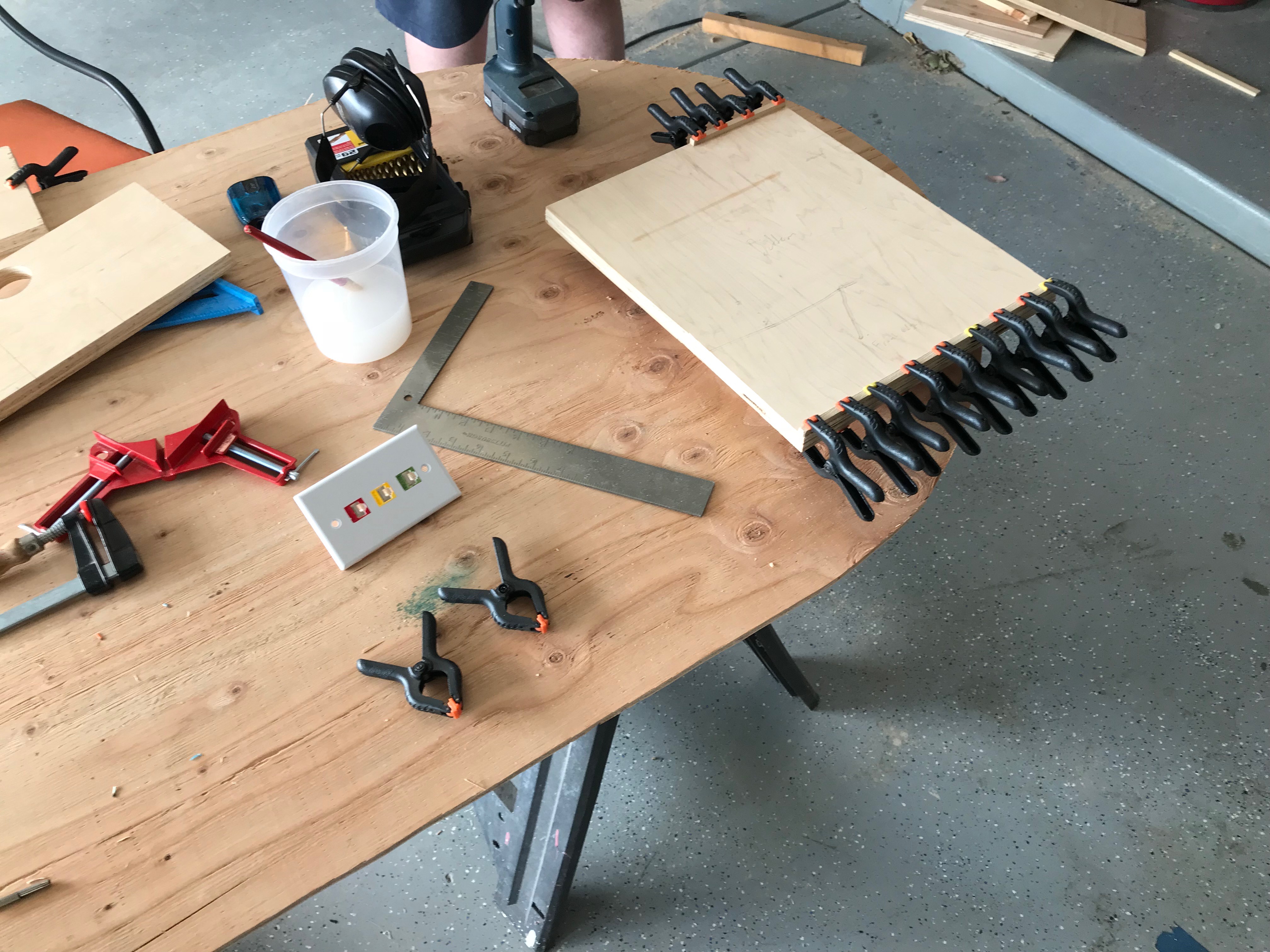
Next came the side panal shelf supports being glued into place. The holes in the sides line up with the vent holes in the DVR. The handles are simple drawer handles purchased at Home Depot.
The following shows the assembly of the box. Attach the sides to the base by gluing and screwing from the bottom.
Attach the back panel. Note the shape of the panel and the large rectangular hole. The shape creates a small alcove area for the baluns and wiring to reside behind the DVR. The shape allows for the rear sliding door and alcove area behind the DVR. This alcove is where all of the cabling attaches when in use. 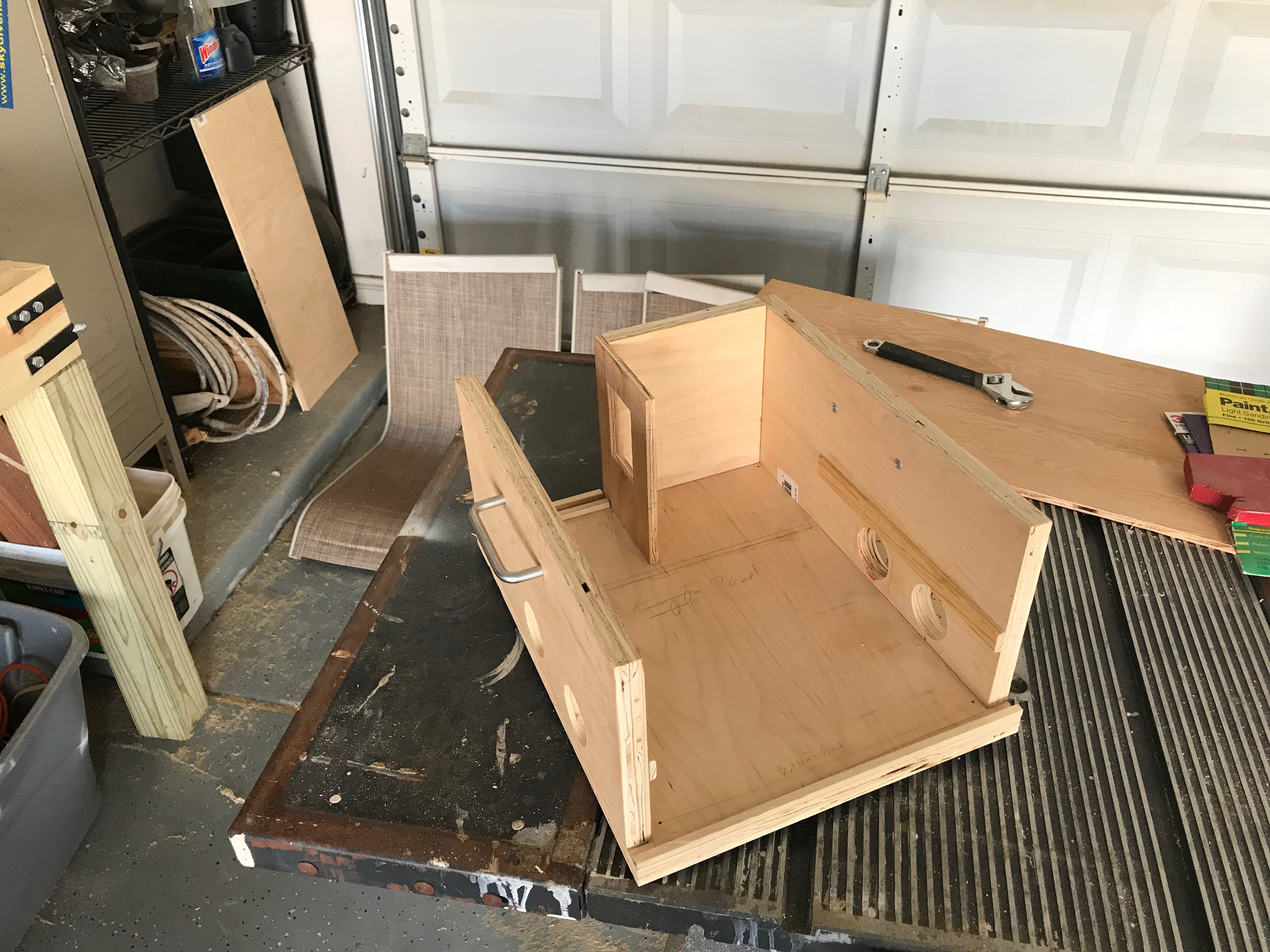
Next we add the inner back panel. This panel also has holes for the wiring to the DVR, and all of the connections needed for monitor, mouse, USB, and power. The tolerances here where very tight and we did sacrifice the HDMI connector by placing the back panel wall directly over the top of it. Since we know we will be using the VGA connection it was no big deal.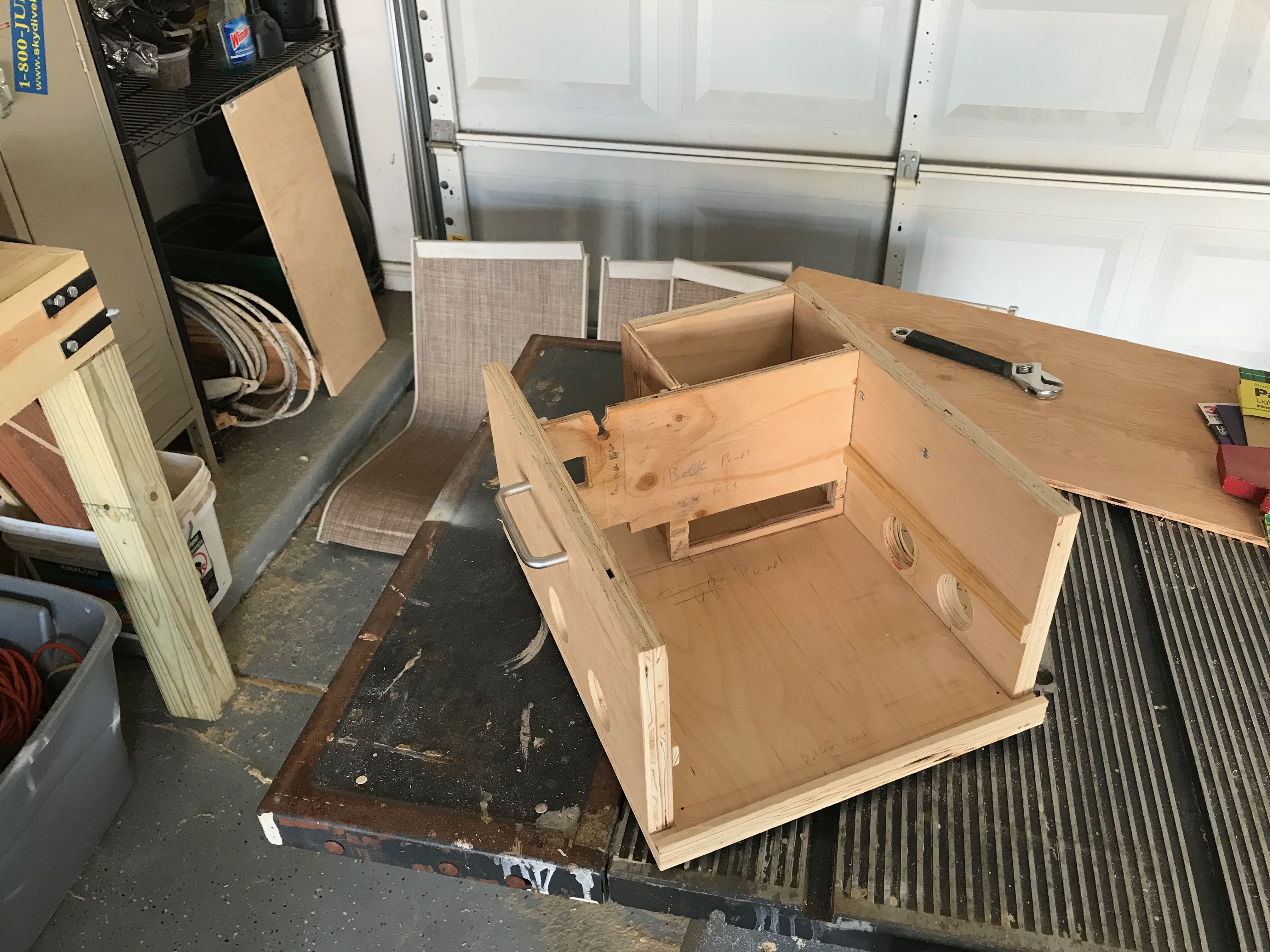
Now add the shelf. The shelf is NOT mounted but is allowed to free float. This was done just in case we need to make modifications in the future. You can also see that the shelf contains a wall and stop block for the table power supply on the left side. 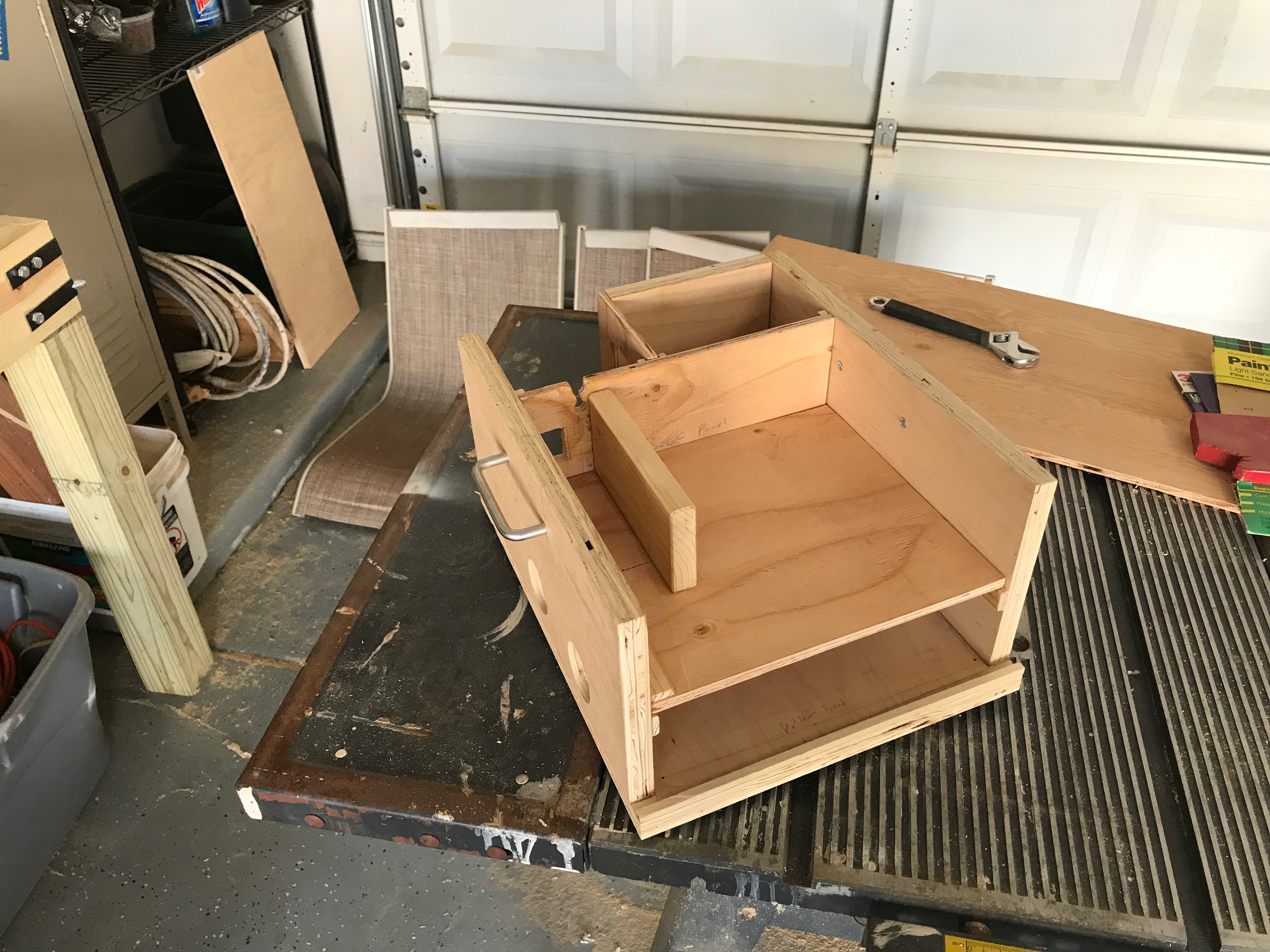
And finally the top with the front sliding door inserted. We decided to NOT glue the top down but to use screws. This provided a means to access the inside should we need to do so.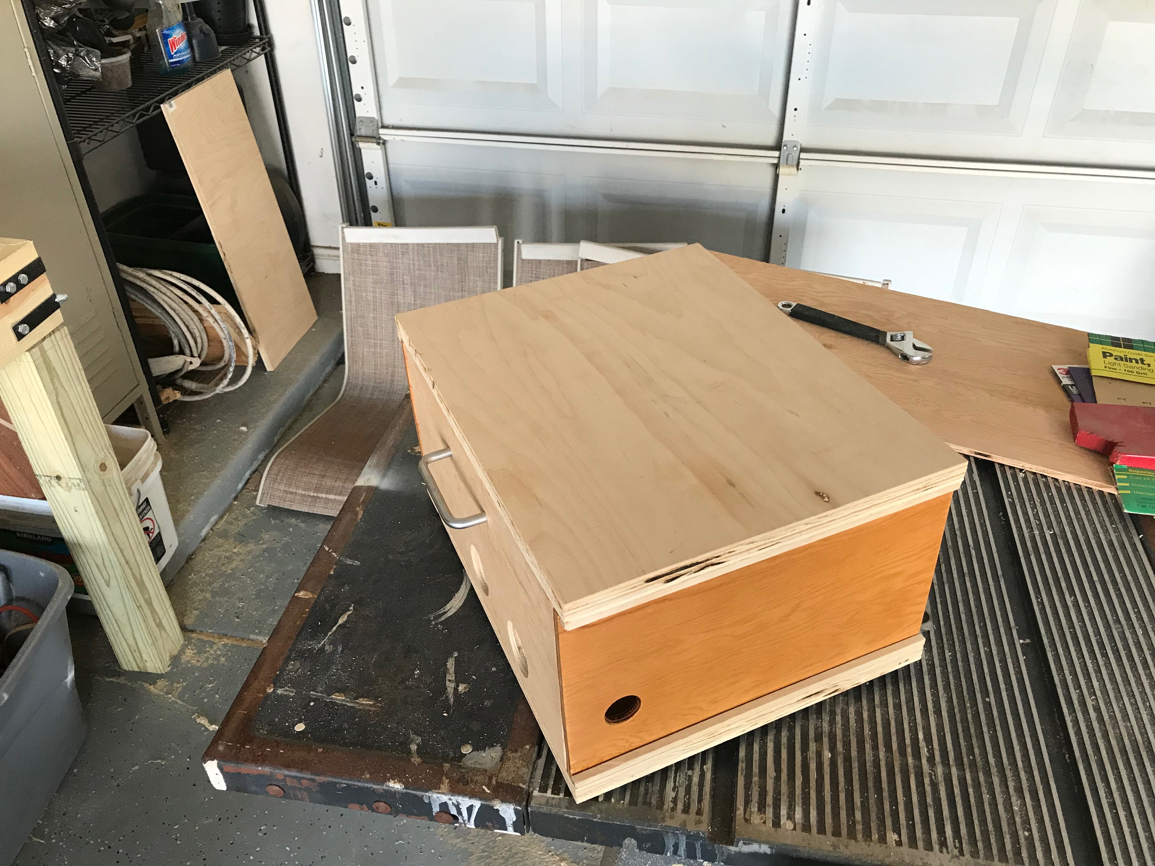
Final Assembly
The last bit was to add the DVR. Remember all of the wires hanging off the back?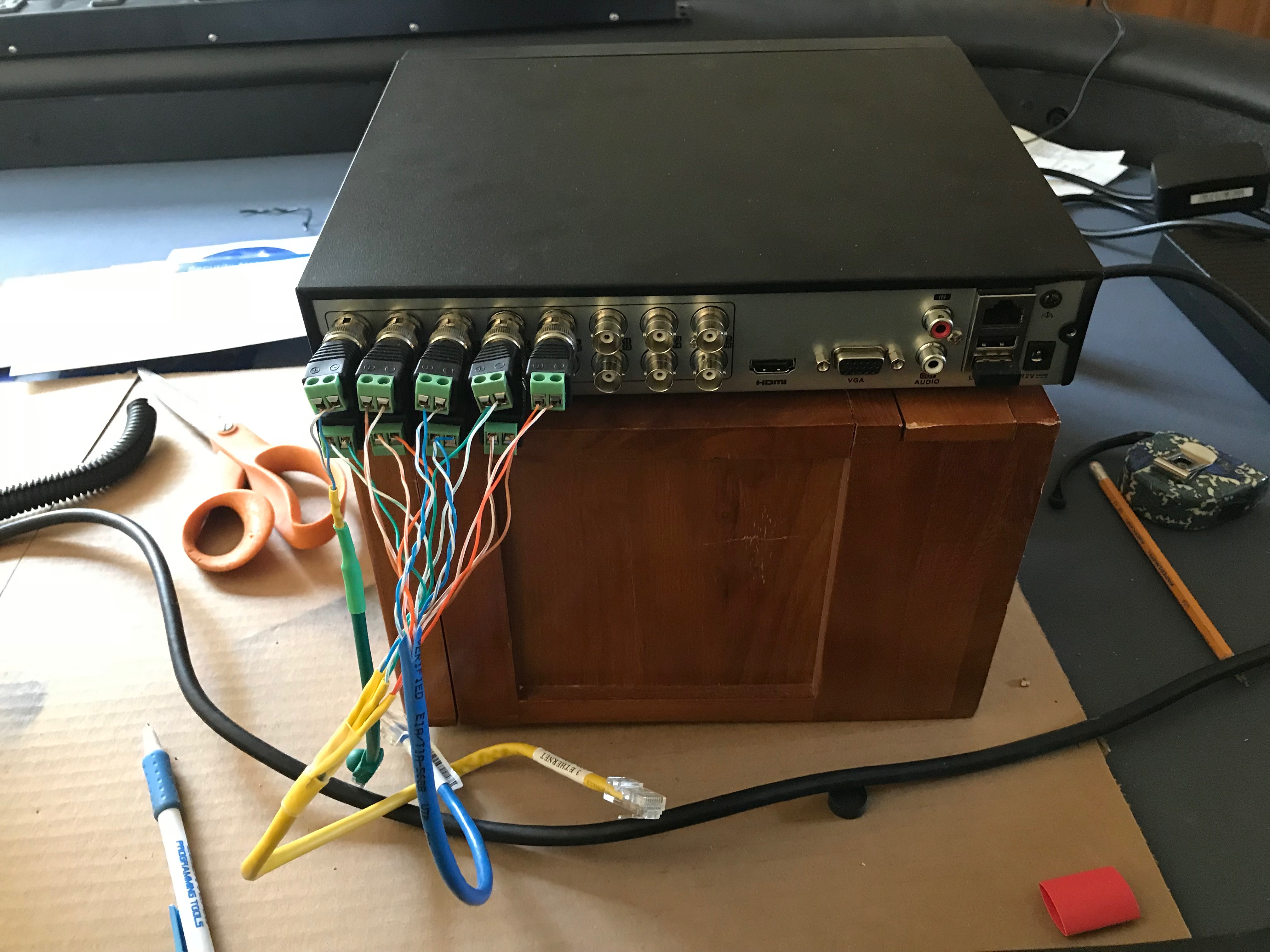
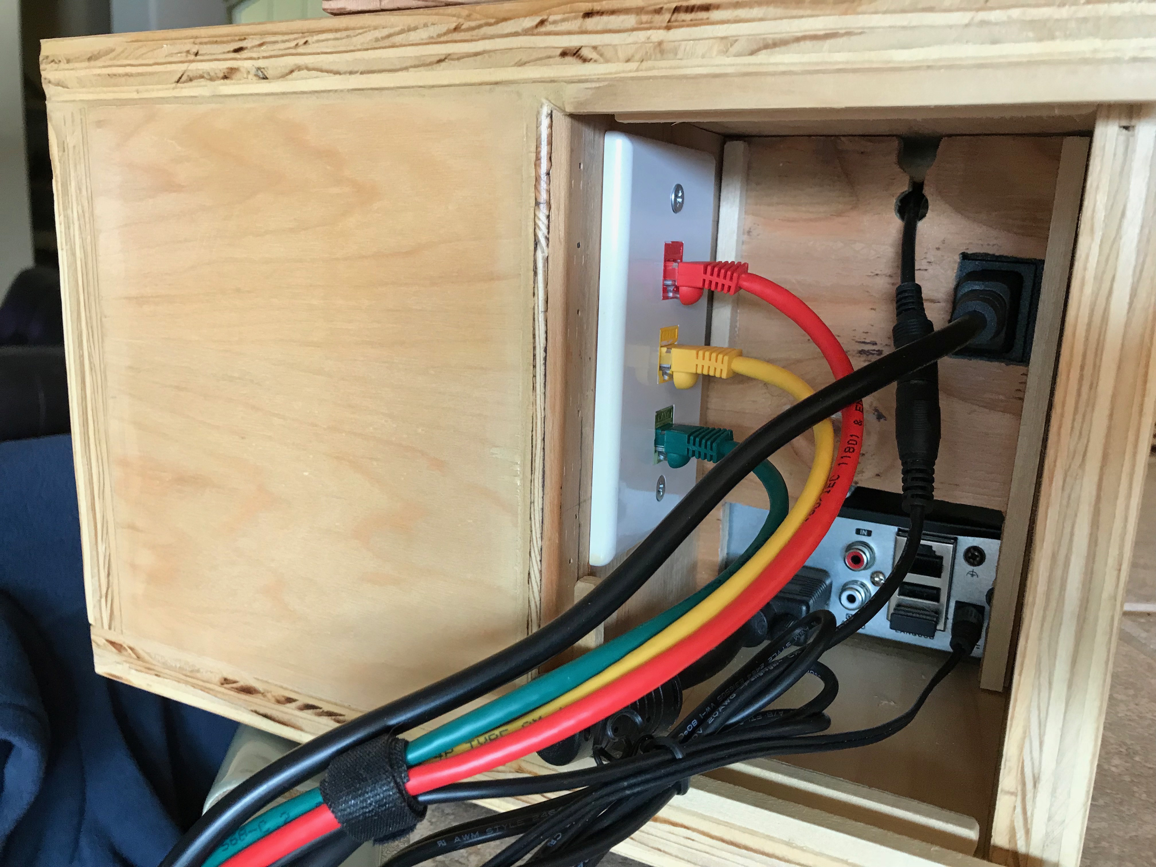
We attaching a faceplate to the inside of the rear panel area (remember the large rectangular hole?) As you can see we colour coded each keystone to match the keystones on the table. This way you just plug the green cat5 into the green plugs and so on.
Already outdated (see below)
With the keystone plate in place we have the following. This area provides storage, during transport, for the DVR power, and the mouse. We changed to a simple wireless mouse that stores with the system.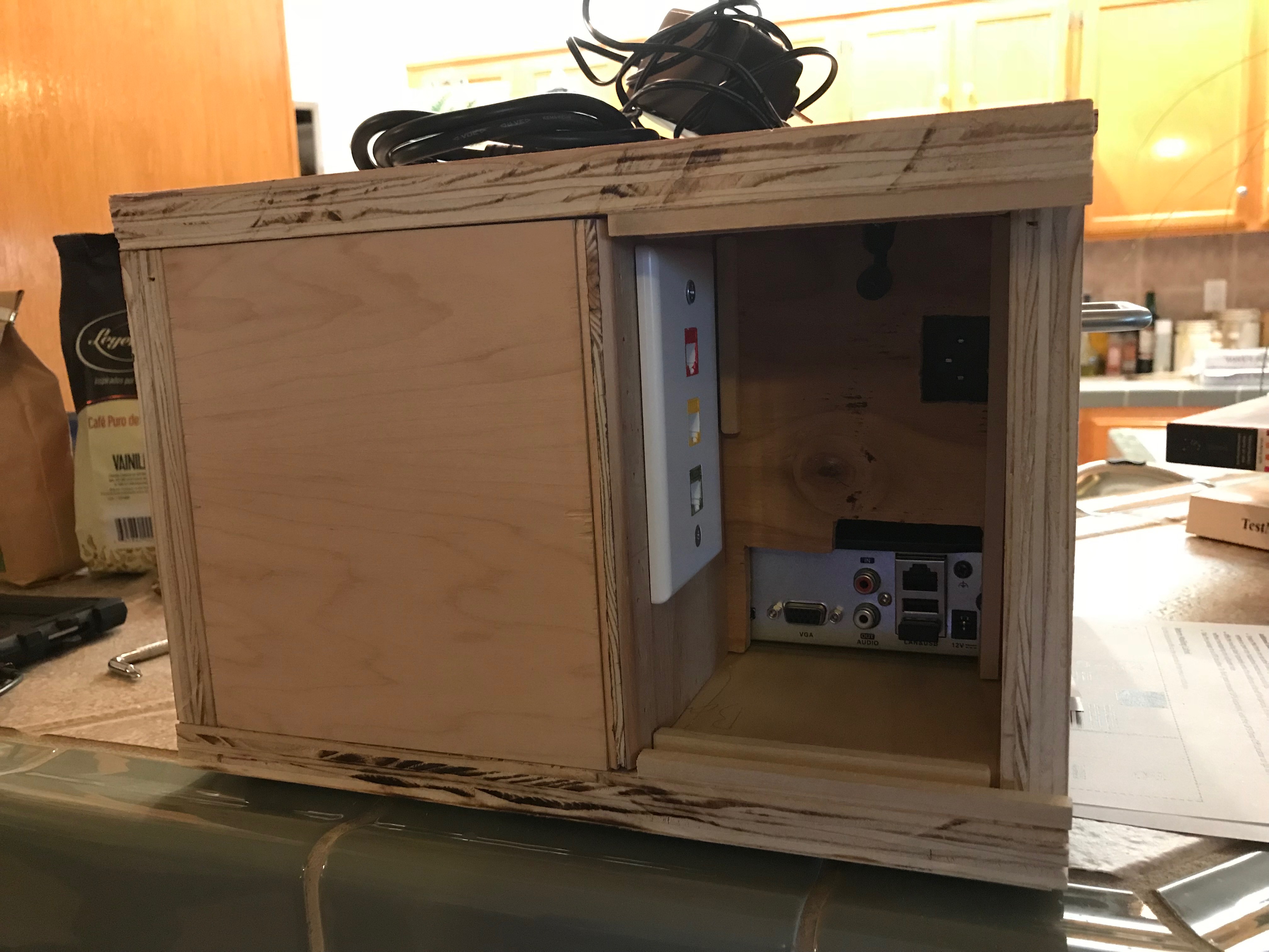
The front view with everything stored inside.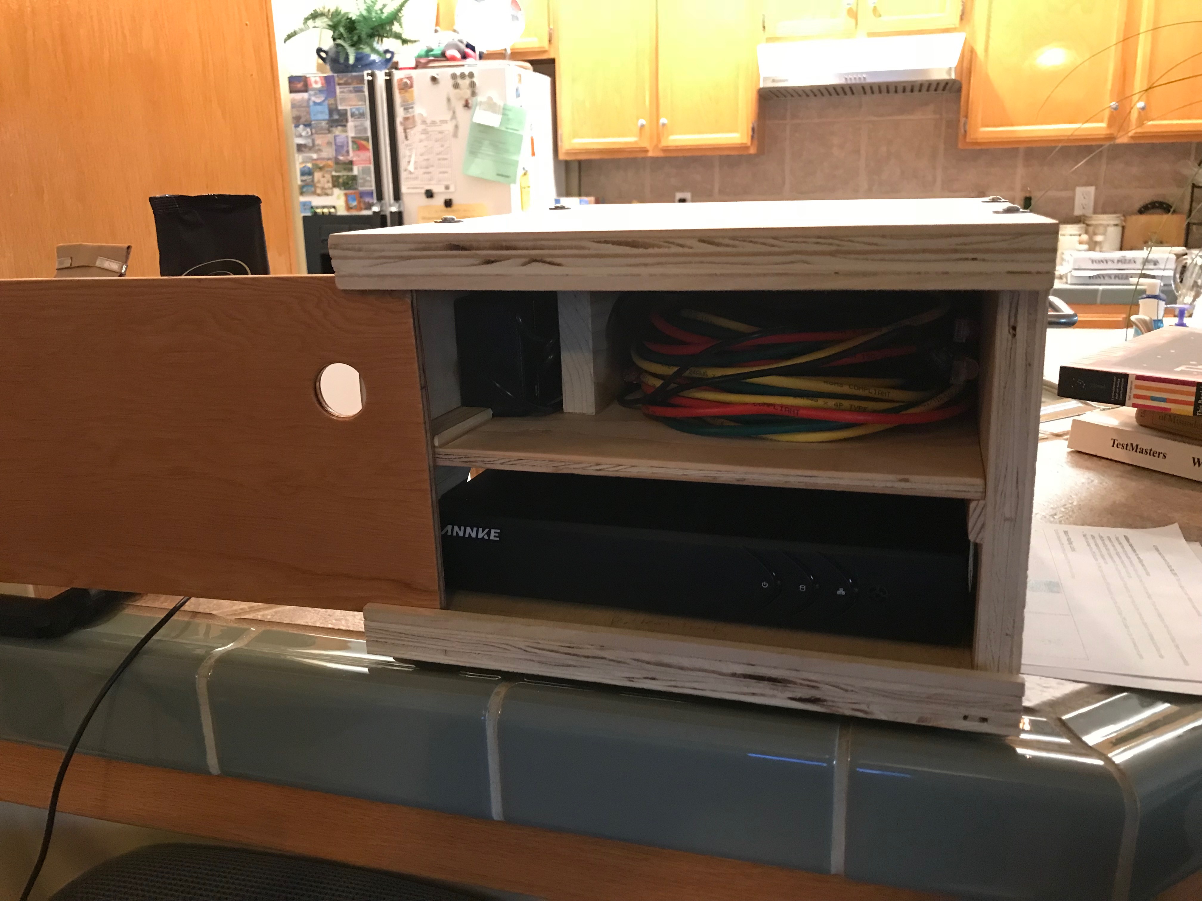
And finally the finished product. Notice the industrial looking screws we added to the top. The bottom uses recessed screws that we then covered with plugs and sanded smooth.
Portable Table
If was found that due to the now elevated height of the padded rail (2 1/2" rise due to camera track) that when the poker table top is placed upon a standard height table (29" high) it felt a bit odd. Because of the now awkward feel of the table we decided to purchase a 6' long folding table from Home Depot and cut down the legs. Yes we wrecked a perfectly good table.
We choose to NOT get a table that also folded in half as this would, by mutual agreement, make the table less stable when in use. As the poker table top needs to be transported it is not a big deal to transport the 6' table with it.
So, as the table top is now 2.5 inches higher - we cut the table legs down 1.25" to "split the difference". It was felt that we could always cut the legs again if needed. As the legs are at an angle near the floor we made a small jig to set the length needed and then transferred this to the other legs. A quick drimel tooling and the job was done.
We wanted to attach the poker table top to this new "dedicated" folding table and the first thought was a make simple L bracket. This meant drilling into the side of the table and through the tables support frame. Ultimately we fabricated these:

Simple flat stock metal bent into shape and welded to a cut down hinge, again from Home Depot. (Note: We are not welders!) Now we can insert the end between the portable table plastic top and the support frame, pivot the hinge to place the bracket around the portable tables edge/frame, and using a hex screw (Budget Bolt) attached to the poker table top.

These attachment points, which there are 4, where originally meant for hanging the poker table top on the wall. You can see on unused bolting location closer to the end of the table (away from the bracket). These where part of the orginal poker table build.
The last thing we did was to replace the hex key bolts with low profile knobs so that we did not need the allen wrench during assembly. (no shown) The brackets and bolting stores away in the box when not in use.
Overhead Cameras
After the first year of using the hole cameras we say the need to have a better overhead camera presents. Like always we thought about it for some time. Not for the cost or complexity but for the easy of installation. We needed something that was fairly light weight and could be incorporated into the BOX.
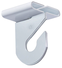
The ceiling over the table is a drop ceiling and, amazingly, slopes up a 10 degree angle. As such the unit had to be less than 6 pounds and we struggled with out to get it high enough to get the coverage. In the end we found these drop ceiling hooks that would allow direct mounting of the unit via eyebolts.
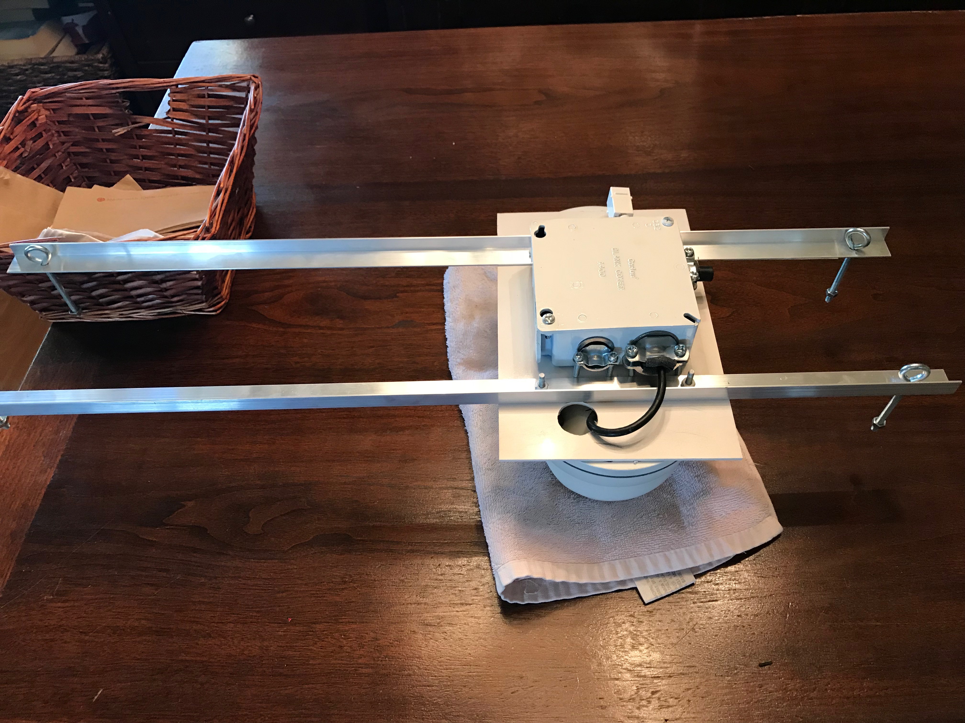
We knew that two cameras would be needed and that we wanted them in the center. The guys at Bakersfield Plastic cut a piece of white PVC and we began the mounting process.
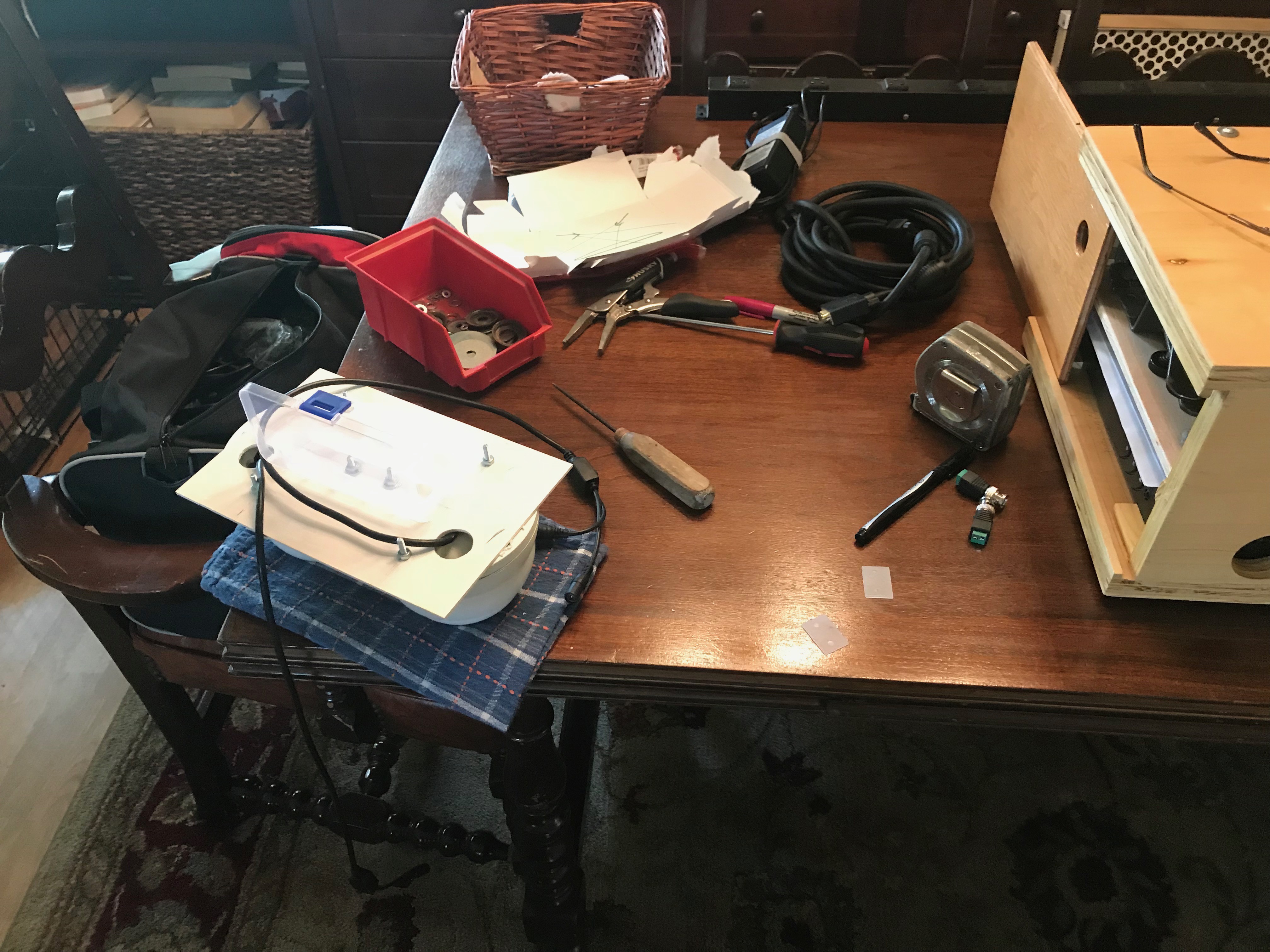
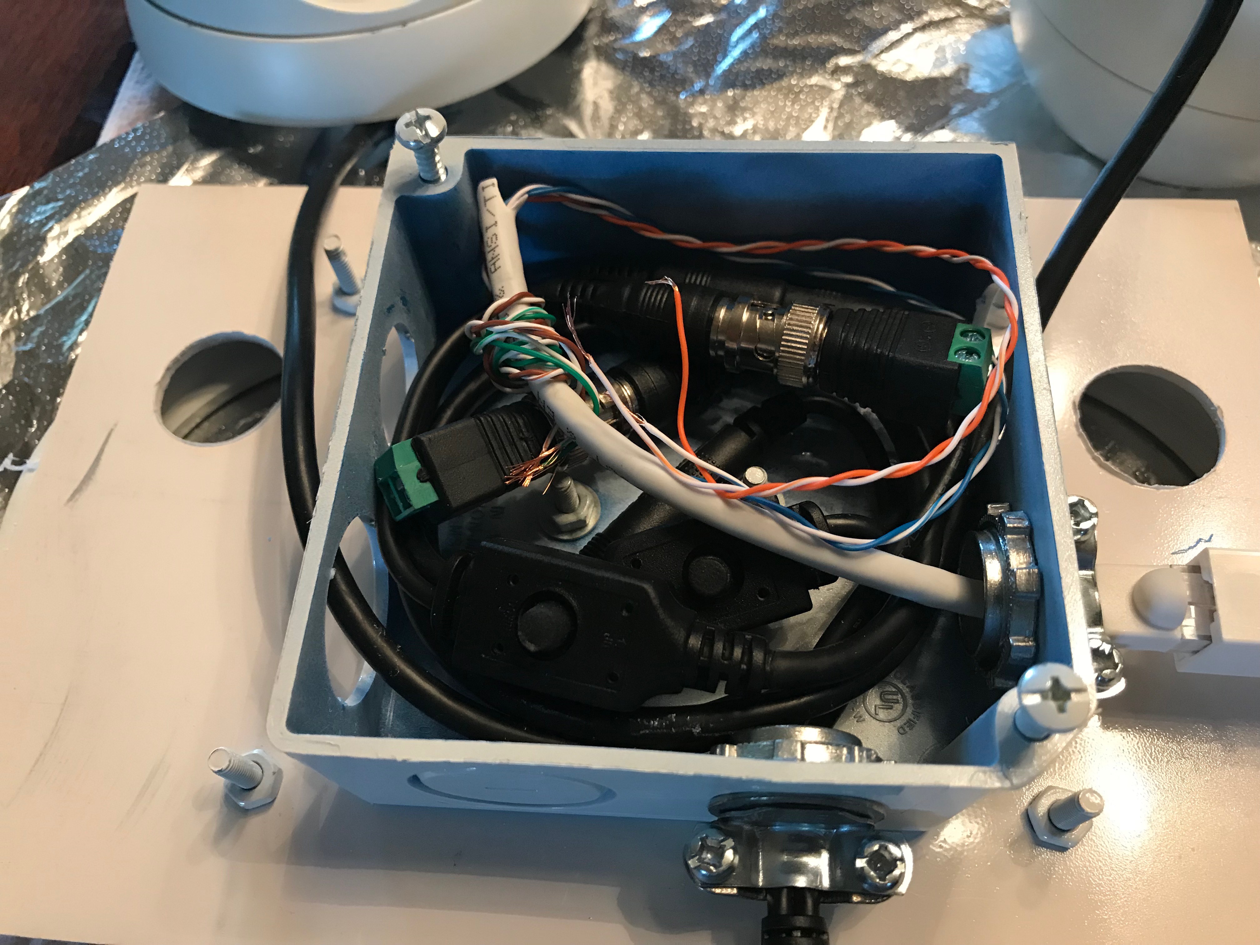
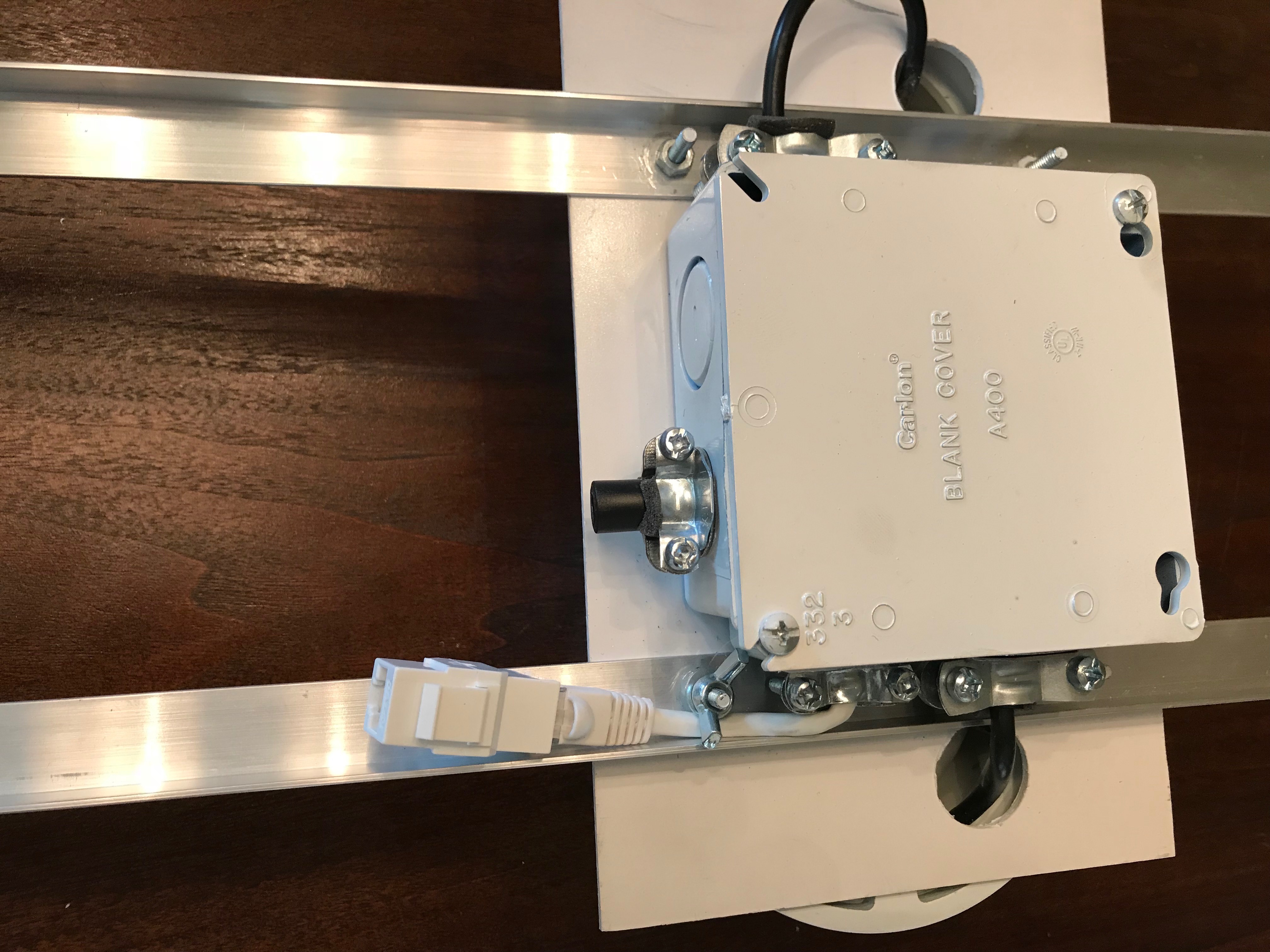
Adding a 2 gang plastic connection box to the top side allows all of the cables to be contained. Using a "standard" off the shelf box allowed for cable clamps to be used which really did help with the cable management. Below is the test fit for the cables.
Once we knew we were on the right path it was time to mount the rails that would hold the platform to the ceiling hooks. OF COURSE we had to undo the bolting that held the cameras to the platform as they were also to hold the rails. While this is the strongest arrangement it did feel like we took 2 steps back for the 1 step forward. It was the right move however and obly took about 20 minutes.
In the previous photos you can see the network (Cat5) cable come out of the side. We considered moving the network cable to the same side but then the people under the rig would see more of the cabling that we like. The solution was actually very easy. We loosened the cable clamp, pull out some slack, retightened the clamp and then used a wing nut to secure it to the same post that holds the rail.
Once the rig was built it was time to modify the BOX and to see of everything still worked. First was adding the new baluns to the back of the DVR and connecting the internal Cat5 to the back of the new keystone plate. Color coding this time was quite easy!
After, and with great stress, we powered up the new cameras and the DVR to see of everything was a go.
One small issue is that we plugged in the baluns to the wrong channels. We wanted to use channels 11 and 12 but wound up on 11 and 13. Obviously this is not important but we may fix this by opening up the back of the rig and swapping wires later. (or not) The DVR only records channels when there are inputs.
Visitors to the site will see the product of this work in future tournament videos.
As always, thank you for your time in reading this!
Use of System
Well if you made it this far then we should tell you how the system is assembled for use. The process is actually very simple due to the equipment used.
Step 1. Unload all cables and mouse from the box.
Step 2. Plug in the monitor and power cables into the rear of the box. The mouse bluetooth USB adapter stays in the USB slot full time.
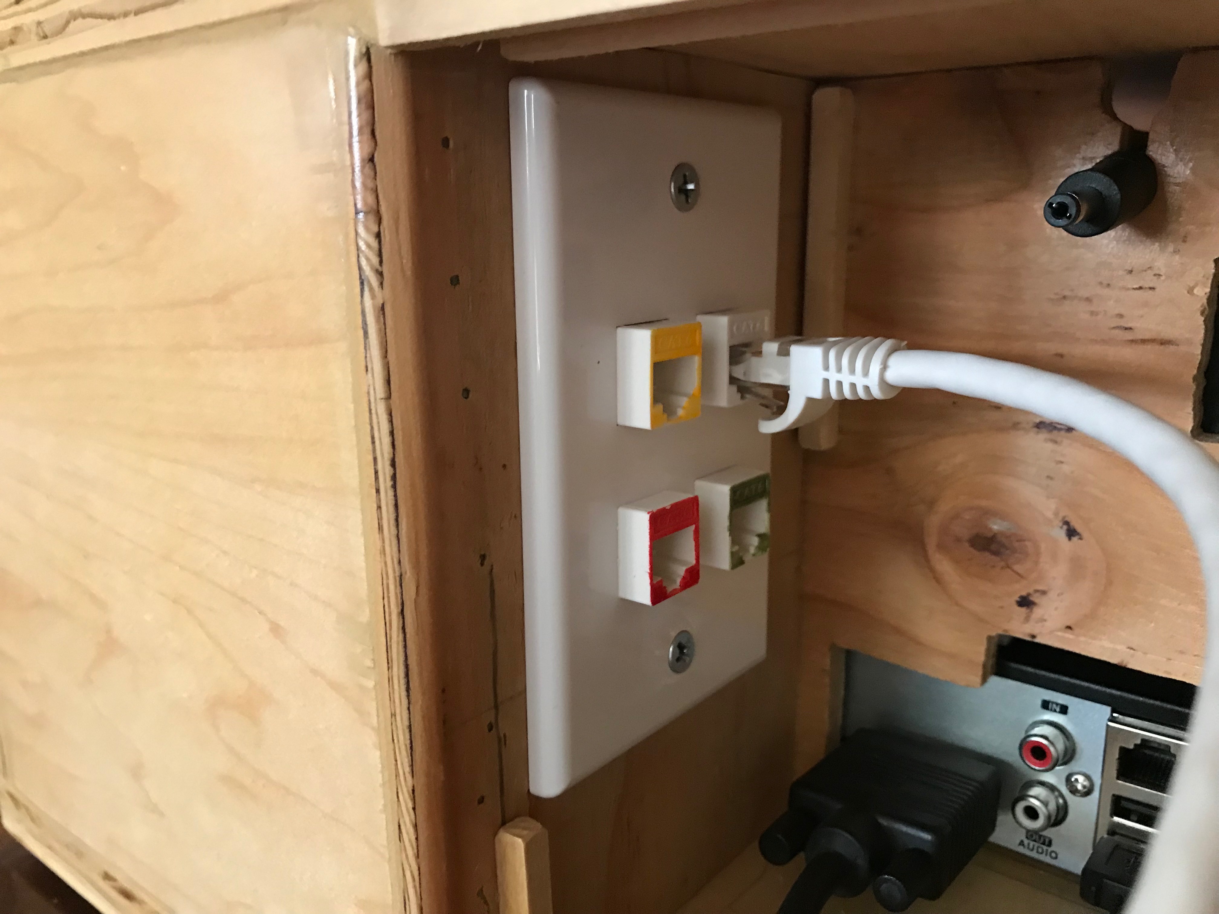
Step 3. Plug in the network cables into the box keystones. They are colour coded.
Step 4. Plug in the network cables and power extension into the table. Again they are colour coded.
Step 5. Plug in the power cable plugs (DVR, table, overhead, and monitor) into a power strip, and the strip into an outlet. (new overhead camera cable not shown)
6. Hang the overhead camera rig on the drop ceiling tee-bars and plug in the power and Cat 5.
Final Step. Switch on the power strip and see the green LED on the table light up. (AKA - And the monkey flips the switch) The 10amp power sources will power the table instantly as there are no switches in the system. We thought about this for some time with the idea of adding some cool switch to the table connection point (think fighter jet switch with cover). This would add more wiring to the already cramped area and in the end the idea was abandoned. The DVR will power up and start recording automatically. Again this is basically a home security system and is designed to auto record.
The DVR software allows for basic customization of the video capture but we left the defaults in place as they already denoted the camera number in the corner of the image. There is truely nothing to do at this point as the system is simply automatic. You may have noticed that we do not use a keyboard. The DVR has a virtual keyboard where needed which is not often.
At the end of the recording session (end of tournament) use the mouse to power down the DVR and stow all of the cables. I have not tested the system to see if the power could just be turned off to power down, but at this time its only a 10 second savings and we thought it best to follow the DVR documentation.
When its time to retrieve the files, power the DVR and plug in a USB memory stick (thumb drive). The system allows you to search by date/time and to select which camera(s) to export. Exporting can be in MPEG or AVI format.
We are using a combination of Hampster (video file conversion) and Hitfilm to edit our videos. Both are free and very powerful with a short learning curve.
Final comments: The combination of Amazon, Fry's Electronics, and Home Depot is a dangerous thing. :) This was a great project and we are pleased with the results.
Thank you for looking over our project.
Josh Farler Foundation
The following list is comlete as we can recall as we did not keep all receipts. Prices are pretax and rounded to nearest whole value. There may be some small items missing but..
| Items | Price in USD | Source | |
| Video Table | |||
| 1 | Donor table | $0 (180) | built by us previously |
| 2 | Cameras (9) | $123 | https://goo.gl/9pAXhH |
| 3 | Video Baluns (2-10 packs) | $30 | https://goo.gl/XQERsM |
| 4 | Power Baluns (10 pack) | $7 | https://goo.gl/M5ygYt |
| 5 | DVR | $169 | https://goo.gl/LLPv49 |
| 6 | 10amp power supply | $18 | https://goo.gl/z9WeRo |
| 7 | LED light | $8 | https://goo.gl/myUP5V |
| 8 | 2:1 splitter with ext cable | $8 | https://goo.gl/NqBvFv |
| 9 | 5:1 spliter (2 needed) | $10 | https://goo.gl/SS4J4q |
| 10 | Nuts/Bolts | $24 | Budget Bolt |
| 11 | Camera mount bracket (2 packs) | $8 | https://goo.gl/2XqfSU |
| 12 | Plastic inner/exterior covering | $40 | Bakersfield Plastics |
| 13 | Screws to mount plastic covering | $15 | O'Rielly's automotive |
| 14 | Foam strip (3 needed) | $15 | https://goo.gl/gFJcLR |
| 15 | Mouse | $11 | https://goo.gl/TYDqWP |
| 16 | Doorbell wire | $11 | https://goo.gl/apYqoe |
| 17 | Misc (screws, glue, wood, paint ) | $40 | Various |
| 18 | Coloured network cables and connectors | $30 | Fry's Electronics |
| 19 | Hinges | $8 | https://goo.gl/YvK2hc |
| 20 | Portable 6' table | $60 | https://goo.gl/Q94sWx |
| Subtotal - rough total | $625 | ||
| Overhead Camera rig | |||
| 21 | Dome cameras (2) | $76 | https://goo.gl/DdBHBi |
| 22 | Power Cables for cameras (2) | $16 | https://goo.gl/MvX2qP |
| 23 | Baluns, keystone, plate, 25' Cat5 | $30 | Fry's Electronics |
| 24 | Aluminum angle stock | $10 | Home Depot |
| 25 | Plastic for camera mounting plate | $5 | Bakersfield Plastics |
| 26 | Electrical box, cable clamps, misc | $13 | Home Depot |
| Subtotal - rough total | $150 | ||
| Total for entire system | $775 |
Results of all this work
To see the results of our work please check out the 2018 Summary page and scroll to the bottom.
For information related to editing the Hole Camera videos click HERE.
Thank you for taking the time to read this!
- Josh Farler Foundation